Beams, Torsion & Deflection
Beams in bending and shafts in torsion: shear and moment diagrams first, a worked cantilever, why turning a bar on edge cuts deflection ninefold, torque in circular shafts, deflection as part of the error budget, and a worked bookshelf in pine and oak.
- 6 min
- 7 steps
- 3 questions
- Lesson 35 of 36
In this lesson
- Read shear and moment before calculating stress
- Worked cantilever
- Worked example: a bookshelf
- Torsion in a circular shaft
- Deflection belongs in the error budget
- Verify stiffness where the function lives
Picking up where you left off.
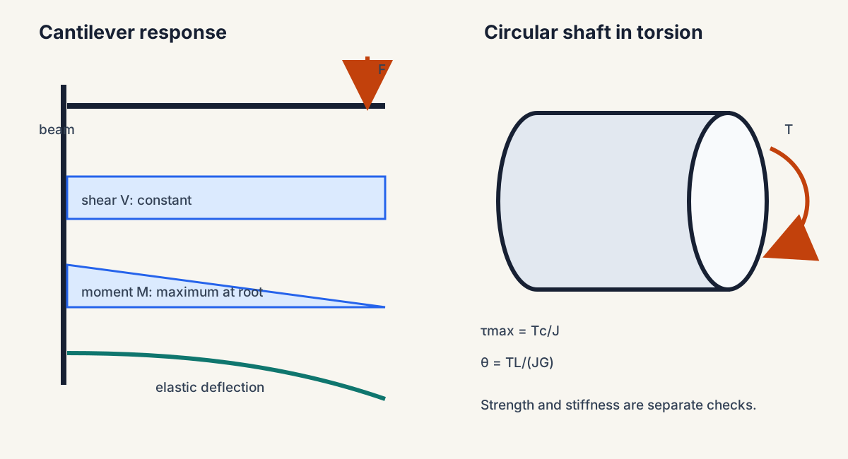
A robot rail can remain below yield yet deflect enough to miss a hole. A shaft can survive torque yet twist enough to destabilize a control loop. Mechanical design therefore checks both strength and stiffness.
MIT’s mechanics-of-materials course treats internal shear, moment, stress, slope, and deflection as one connected model 1. Carry the same load case through every layer rather than borrowing a maximum moment from one case and a boundary condition from another.
Read shear and moment before calculating stress
For distributed transverse load \(w(x)\), shear \(V(x)\), and bending moment \(M(x)\), the sign-convention-dependent relationships are
Point loads create jumps in shear; applied couples create jumps in moment. Extrema of moment occur where shear crosses zero or at boundaries. The bending stress estimate is
so material far from the neutral axis contributes disproportionately through the second moment of area \(I\). That is why tubes and I-sections can be stiff for their mass.
Boundary conditions close the problem. A fixed end has zero slope and displacement; a simple support has zero displacement but permits rotation; a free end carries the specified shear and moment. For small linear-elastic bending,
Integrate twice and apply the actual boundary conditions. Superposition is allowed only when geometry, material response, and boundary behavior remain sufficiently linear. It is a convenience, not permission to combine incompatible models.
Worked cantilever
A 300 mm cantilever carries 100 N at its tip. Its rectangular cross-section is 30 mm wide and 10 mm deep in the bending direction.
- Root moment: \(M=FL=30{,}000\) N·mm.
- \(I=bh^3/12=30(10^3)/12=2500\) mm\(^4\).
- Extreme-fiber stress: \(\sigma=Mc/I=30{,}000(5)/2500=60\) MPa.
- For \(E=70{,}000\) MPa, end deflection \(\delta=FL^3/(3EI)=5.14\) mm.
Rotating the same bar so 30 mm is the depth raises \(I\) by a factor of nine and cuts deflection to about 0.57 mm. Orientation changed performance without adding material.
That improvement is directional. The deep flat bar may be weak laterally and poor in torsion. A closed tube often offers a better multi-axis compromise, while an open channel may need bracing or careful load introduction to avoid twist. Place material far from the neutral axis, but also preserve local wall stability and manufacturable joints.
Worked example: a bookshelf
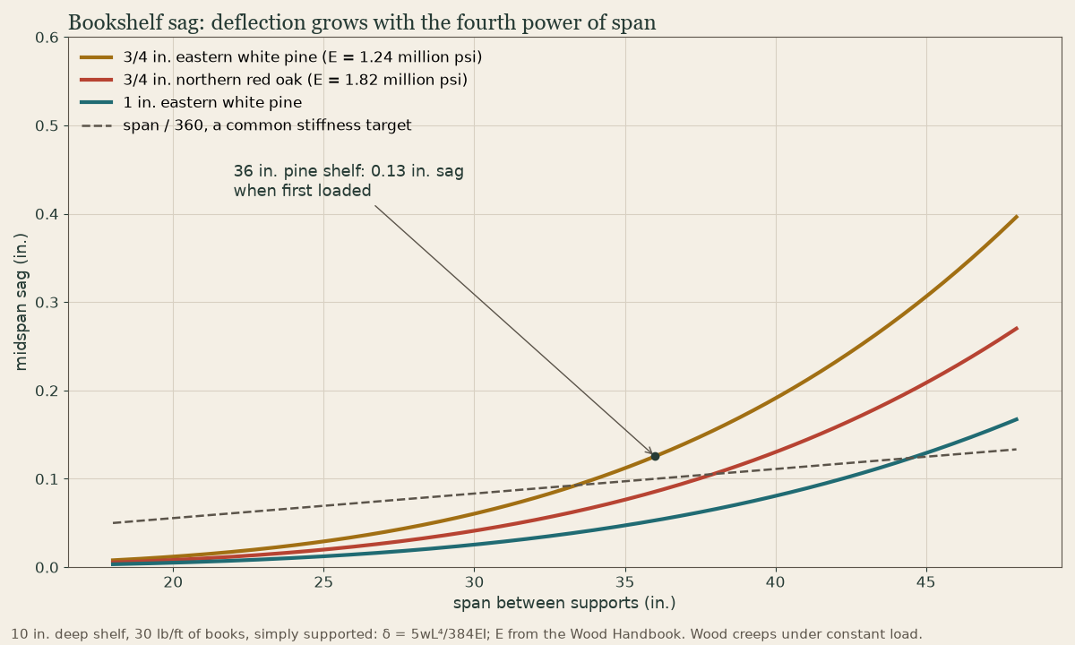
A wooden shelf is a uniformly loaded, simply supported beam, with midspan deflection
Take a 3/4 x 10 in. eastern white pine shelf spanning 36 in., loaded with books at about 30 lb per foot (2.5 lb/in.). The Wood Handbook gives eastern white pine a modulus of elasticity of about 1.24 million psi at 12% moisture content 2.
- \(I = bh^3/12 = 10(0.75)^3/12 = 0.352\) in.\(^4\)
- \(\delta = 5(2.5)(36)^4 / [384(1{,}240{,}000)(0.352)] \approx 0.13\) in.
That’s visible, and wood creeps: under a constant load, the sag keeps growing for months. Three fixes, in order of power:
- Shorten the span: deflection goes with \(L^4\), so cutting 36 in. to 30 in. reduces sag by half.
- Thicken the shelf: going from 3/4 in. to 1 in. raises \(I\) by \((1/0.75)^3 \approx 2.4\).
- Stiffer wood: northern red oak, at about 1.82 million psi 2, cuts the sag by about a third.
A hardwood nosing strip glued edge-up along the front adds depth exactly where it helps, the same trick as turning the cantilever bar on edge.
Quick check
(30/36)⁴ ≈ 0.48.
Torsion in a circular shaft
For a solid circular shaft under torque \(T\),
where \(J=\pi d^4/32\). The fourth-power dependence makes diameter powerful. Shoulders, keyways, splines, hollow sections, and noncircular shafts require refined models.
MIT’s machine-design materials frame shaft sizing as a system problem involving torque, bending, stress concentration, bearings, couplings, and fatigue—not torsion in isolation 3. A hollow circular shaft can retain high torsional stiffness per unit mass because material near the center contributes little to \(J\). Thin-walled closed sections carry torsion efficiently; open thin-walled sections generally do not.
For a drivetrain, include angular windup from every compliant element: shafts, couplings, belts, gears, bearings, and structure. Backlash and compliance are different: backlash creates a dead zone; elastic compliance creates load-dependent position error and a resonance.
Deflection belongs in the error budget
Add predicted elastic motion to bearing clearance, manufacturing tolerance, thermal growth, foundation motion, sensor error, and control following error. If a pick must land within ±0.5 mm, a nominal 0.4 mm frame deflection is not “small”; it consumes most of the allowance.
Do not add every error worst-case unless the specification demands it; classify errors as bias, repeatability, drift, or random variation and state the combination method. Also distinguish tool deflection measured relative to the base from absolute base motion. A sensor mounted on the same flexible member may hide motion that an external reference sees.
Verify stiffness where the function lives
Calculate at the critical load case, then measure at the tool, bearing, sensor, or interface whose alignment matters. Use a known load and a displacement indicator or calibrated sensor. Compare the measured slope of load versus displacement with the model, unload to check permanent set, and investigate hysteresis that may indicate joint slip or backlash.
A coarse beam model is valuable early. As geometry and joints become detailed, refine only the uncertainties that affect the decision: local stress near a weld, bearing-seat rotation, plate distortion, or contact compliance. Model fidelity should follow consequence and sensitivity.
Design exercise
Compare three cross-sections of equal area—a flat bar, a deep rectangular tube, and a square bar—for a horizontal sensor arm. Calculate or estimate \(I\), stress, and end deflection. Then record tradeoffs in access, joining, lateral and torsional stiffness, local buckling, cable routing, and cost. Propose a bench test at the sensor mounting face and define an allowable load-deflection slope before testing.
Practice
Cantilever end deflection varies inversely with flexural rigidity EI.
Practice
Functional stiffness limits can be more restrictive than material strength.
Lesson complete
Nice work.
Sources for this lesson
- 1Mechanics of Materials. MIT OpenCourseWare. verifiedOpen modules on stress, strain, trusses, torsion, bending, deflection, yielding, fracture, fatigue, and material properties. Cited at: beam loading and deformation.
- 2Robert J. Ross. Wood Handbook: Wood as an Engineering Material. Revised 2021 ed. USDA Forest Service, Forest Products Laboratory. 2021. verifiedOfficial chapters on wood structure, moisture, mechanical properties, fastenings, composites, drying, and finishing.
- 3Elements of Mechanical Design. MIT OpenCourseWare. verifiedModeling, design, integration, fabrication, and characterization of bearings, springs, gears, cams, mechanisms, shafts, drives, and connections. Cited at: shafts and mechanical elements.