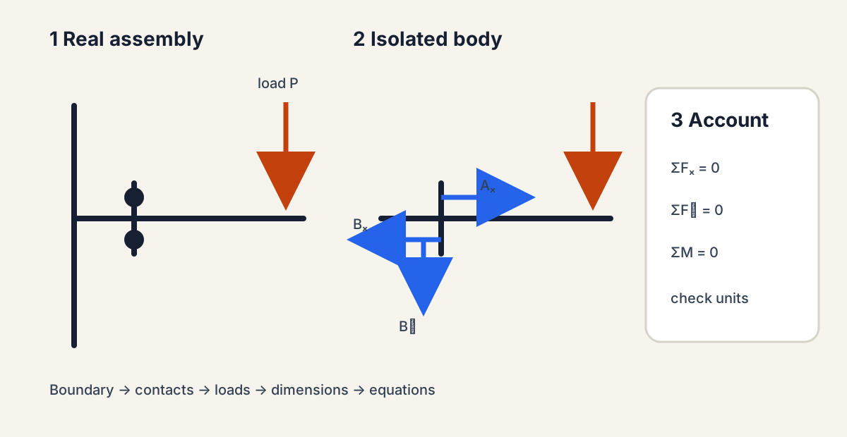
Free-Body Diagrams That Can Be Audited
Free-body diagrams done carefully: forces, points, and lines of action, the boundary-contact-load sequence, checking that supports actually constrain the body, a worked bracket, separating an assembly into bodies, and the checks that catch most mistakes.
- 6 min
- 8 steps
- 3 questions
- Lesson 31 of 78
In this lesson
- Keep forces, points, and lines of action distinct
- Use the boundary-contact-load sequence
- Check whether the constraints make sense
- Worked bracket example
- Whole assembly, then separate bodies
- Three checks that catch most mistakes
- Escalate the model when the assumption matters
Open alongside this lesson
-
Mechanics of Materials (opens in a new tab)
Use the truss, equilibrium, and bending modules after completing the in-app examples.
Picking up where you left off.
A correct answer can come from a bad diagram by accident. A free-body diagram (FBD) makes the reasoning inspectable: isolate one body, erase its surroundings, and replace each removed contact with the force or moment that the surroundings exert on the body. MIT’s mechanics-of-materials sequence treats equilibrium as the bridge between applied load and internal stress 1.
An FBD is also a model contract. It states which body is rigid, which contacts are idealized, which loads are external, and which dimensions determine moment arms. OpenStax’s force treatment reinforces the same vector discipline: forces must be resolved and summed by direction rather than by magnitude alone 2.
Keep forces, points, and lines of action distinct
Draw the arrow on the body at the point or region where the interaction enters. Label magnitude, direction, and point of application. A force can be moved along its own line of action for rigid-body equilibrium, but shifting it to a parallel line adds a moment. A couple moment has magnitude and rotation sense but no unique point of application.
Resolve an angled force only after its angle convention is clear. If an 800 N actuator pulls 35 degrees above the horizontal,
Those components are not two new loads; they are one load expressed in the chosen axes. Keep the original line of action visible so the moment is not accidentally calculated from the wrong component distance.
Use the boundary-contact-load sequence
- Boundary: name the one body or assembly being analyzed.
- Contacts: replace pins, rollers, cables, bearings, and fixed supports with their allowed reactions.
- Loads: add weight, applied forces, applied couples, pressure resultants, and known spring forces.
- Axes and dimensions: show a coordinate system and the perpendicular distances needed for moments.
- Equilibrium: only now write \(\sum F_x=0\), \(\sum F_y=0\), and \(\sum M_O=0\).
A pin in planar analysis can usually exert two force components but no independent reaction moment. A roller reacts normal to its surface. A cable pulls along itself. A fixed support can exert two force components and a moment. These are idealizations; a real bolted foot, bearing, or weld distributes stress over area.
Check whether the constraints make sense
A planar rigid body supplies three independent equilibrium equations. Compare them with the unknown reaction components, but do not stop at counting. Too few independent constraints allow rigid-body motion; too many reaction unknowns make the problem statically indeterminate; poorly placed constraints can be geometrically unstable even when the count looks correct.
Examples:
- two rollers on parallel horizontal surfaces cannot resist a horizontal load;
- three reaction lines meeting at one point cannot resist an independent applied couple;
- two fixed supports provide more unknown reactions than planar equilibrium alone can determine;
- a tension-only cable cannot supply the compression a negative solution would imply.
When the idealization predicts an impossible reaction, revisit the boundary and support model before adding equations.
Worked bracket example
A 400 N downward load acts 0.30 m from a wall-mounted bracket. The upper and lower wall fasteners are 0.12 m apart. If their horizontal forces form the resisting couple, the required force magnitude is approximately
The wall must also supply 400 N of net vertical reaction. This does not yet size either fastener: preload, slip, plate bending, load sharing, edge distance, and fastener-group geometry still matter. Statics determines the external demand; connection analysis distributes it.
Whole assembly, then separate bodies
Begin with the largest useful assembly. Internal pin, gear-contact, or joint forces cancel in the whole-assembly FBD, often making external reactions easy to find. Then separate one member or subassembly; the internal interaction reappears as equal and opposite forces on the two new diagrams.
For each separated pair, use a consistent label such as \(F_{A\rightarrow B}\) and \(F_{B\rightarrow A}=-F_{A\rightarrow B}\). This prevents the same pin force from being drawn in the same direction on both bodies. If friction is included, show the normal force and the friction force separately and justify whether the contact sticks, slips, or is at an impending-slip limit.
Audit table
Before solving, make a small table with interaction, body, point/line, known or unknown, allowed components, and source. Weight comes from mass and gravity; a pressure resultant comes from a pressure field; an actuator force comes from a specified or measured state. This table catches loads copied from a neighboring case without evidence.
Quick check
Newton’s third law; drawing it one way on both bodies is a common error.
Three checks that catch most mistakes
- Units: force equations end in force; moment equations end in force-times-distance.
- Direction: a negative solved reaction means the actual direction opposes the arrow you assumed; it is not automatically an error.
- Second moment center: repeat one moment equation about a different point. The same reactions should satisfy it.
Escalate the model when the assumption matters
Rigid-body statics cannot determine contact pressure, local fastener load sharing, elastic redistribution, or deformation compatibility. If the conclusion depends on those effects, carry the equilibrium result into a connection, beam, finite-element, or test model. The goal is not to make the first FBD elaborate; it is to know exactly what that FBD can and cannot prove.
Practice artifact
Photograph or sketch a wall shelf, robot-base plate, pedal, or hinge. Create two FBDs: the entire assembly and one critical member. Mark which forces are known, which are reactions, and which dimensions are perpendicular moment arms. End with an assumption register—for example, rigid plate, planar loading, negligible self-weight, no slip. That small register is what makes later refinement possible.
Practice
Equations are only trustworthy after the system boundary and external interactions are explicit.
Practice
Sum of forces in x, sum of forces in y, and sum of moments about any point must each be zero.
Lesson complete
Nice work.
Sources for this lesson
- 1Mechanics of Materials. MIT OpenCourseWare. verifiedOpen modules on stress, strain, trusses, torsion, bending, deflection, yielding, fracture, fatigue, and material properties. Cited at: equilibrium and structures.
- 2University Physics, Volumes 1–3. OpenStax (Rice University). verifiedOpen calculus-based physics. Vol 1 mechanics; Vol 2 thermodynamics and electricity & magnetism; Vol 3 optics & modern physics. Cited at: force vectors and equilibrium.