Trusses, Frames & Internal Force
Trusses and frames: the two-force-member idealization, screening stability and determinacy, choosing the method of joints or sections, cutting a frame to expose internal demand, machines and constraint, and reviewing the load path.
- 6 min
- 5 steps
- 3 questions
- Lesson 33 of 78
In this lesson
- Truss idealization
- Cut a frame to expose demand
- Frames, machines, and constraint
- Worked section strategy
Picking up where you left off.
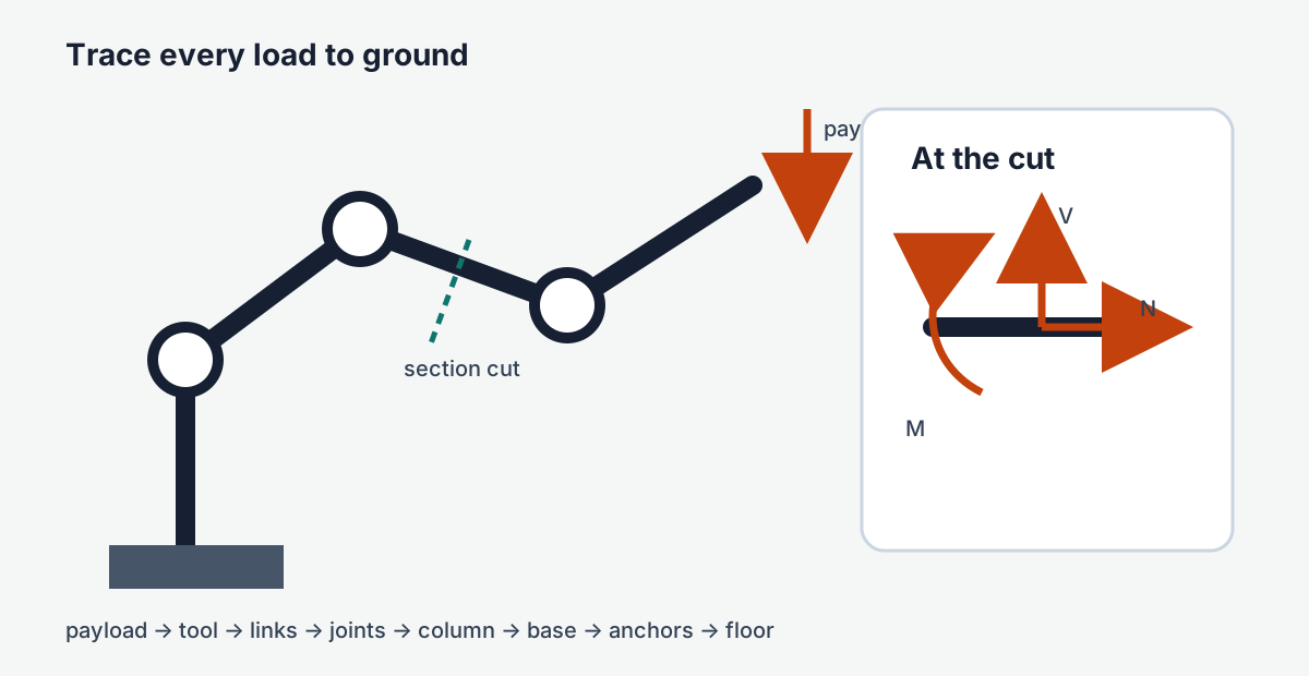
A machine frame is a load path. The payload loads the end effector; the arm carries that demand through joints and links; the base and anchors carry it into the floor. If an analysis stops before reaching ground, it usually hides a connection or assumes an impossibly floating reaction.
MIT’s mechanics-of-materials sequence begins with equilibrium and internal resultants because a material calculation is meaningful only after the load path is defensible 1. Treat every joint, bracket, bearing, and anchor as a transfer point: name what enters, what leaves, and which feature carries it.
Truss idealization
An ideal planar truss has straight members connected by frictionless pins, with external loads applied only at joints. Each member is then a two-force member in axial tension or compression. At a joint, solve \(\sum F_x=0\) and \(\sum F_y=0\). Start where no more than two member forces are unknown.
For a triangular bracket with a 1 m horizontal member and a 1 m vertical rise, a diagonal at 45 degrees supporting a 500 N downward joint load must supply a vertical component of 500 N. Its axial magnitude is \(500/\sin45^\circ=707\) N. Its horizontal component is 500 N and must be balanced by the horizontal member. Whether each is tension or compression follows from the solved arrow directions.
Real frames depart from this model: joints have stiffness, members carry self-weight, loads may enter between joints, and bending appears. The truss result is still useful if its assumptions match the architecture.
Screen stability and determinacy
For a simple planar pin-jointed truss, the count
is a useful first screen, where \(m\) is members, \(r\) is reaction components, and \(j\) is joints. Equality is necessary for a statically determinate simple truss, but not sufficient: poor geometry can still form a mechanism. If \(m+r<2j\), the truss is generally unstable; if \(m+r>2j\), it is generally indeterminate and needs compatibility plus stiffness, not equilibrium alone.
Two zero-force-member rules accelerate hand checks when their assumptions hold:
- at an unloaded joint with two non-collinear members, both are zero-force members;
- at an unloaded joint with three members, two collinear, the non-collinear member is zero-force.
These members may still be important for alternate load cases, buckling restraint, assembly, or dynamic behavior. “Zero in this idealized case” does not mean “safe to delete.”
Choose joints or sections deliberately
The method of joints is efficient when many member forces are needed: solve the support reactions, then move joint by joint from no more than two unknowns. The method of sections is efficient when only a few interior forces matter: pass a cut through no more than three unknown member forces and apply whole-body equilibrium to one side. Choose a moment center that eliminates two cut forces when possible.
Assume unknown members are in tension, pulling away from the isolated joint or cut. A negative result then means compression. This convention keeps the algebra auditable without guessing force sense from appearance.
Quick check
A single cut and three equations can reach a member directly instead of working joint by joint.
Cut a frame to expose demand
At an imaginary cut through a planar member, show three internal resultants:
- axial force \(N\), normal to the cut;
- shear force \(V\), tangent to the cut;
- bending moment \(M\).
Apply equilibrium to either side. The signs on the opposite face reverse because the separated pieces exert equal and opposite actions. The functions \(N(x)\), \(V(x)\), and \(M(x)\) convert the external load story into the inputs needed for stress and deflection.
For a member with an intermediate point load, distributed load, or applied couple, use a piecewise cut. The internal-force functions change only where the loading changes. Check the reconstruction: integrating load changes shear, and integrating shear changes moment. A section result that does not reproduce the boundary reactions or applied couple contains a sign or region error.
Frames, machines, and constraint
A frame contains multi-force members and transmits bending. A machine adds members whose relative motion is intentional. The analysis habit is the same: isolate the full assembly, solve external reactions when possible, then isolate members or subassemblies. Pins internal to the full assembly vanish from its FBD but reappear as equal and opposite forces on the separated pieces.
Real connections decide whether the idealization survives. A clevis pin can develop bearing stress and double shear; a bolted interface may transfer load through preload and friction before it slips into bolt bearing; a welded corner may be much closer to a rigid joint than a pin. Compression members need a buckling check even when their axial stress is modest. Document which connection behavior the global model assumes, then verify the joint locally.
Worked section strategy
Suppose a six-panel roof truss has a center load but the design question concerns one bottom-chord member and two diagonals near midspan. Solving every joint is unnecessary. First solve the two support reactions from the full truss. Then cut through the three target members and isolate the simpler half. Take moments about the intersection of two cut-member lines to solve the third force directly; use \(\sum F_x=0\) and \(\sum F_y=0\) for the rest.
Before accepting the numbers, ask whether the compression diagonal’s unsupported length and end restraint make buckling plausible, whether load truly enters at the modeled joint, and whether the connection can deliver the assumed axial force without eccentricity. Equilibrium supplies member demand; it does not by itself qualify the member or joint.
Load-path review
For a tabletop robot or adjustable monitor arm, draw the load path for three cases: gravity at maximum reach, emergency stop during motion, and a human applying an unintended side force. At every interface ask:
- What force and moment cross here?
- Which feature carries each component—bearing, shoulder, bolt preload, weld, key, or friction?
- What happens if clearance opens or friction is lost?
That review often reveals the real weak point before a stress equation does. Finish by marking each interface verified, needs local calculation, needs test, or assumption only. The resulting map becomes a compact agenda for the next design review.
Practice
With only two endpoint forces and equilibrium, the forces must be equal, opposite, and collinear, producing tension or compression.
Practice
A section cut replaces the removed material with the internal resultants it transmitted.
Lesson complete
Nice work.
Sources for this lesson
- 1Mechanics of Materials. MIT OpenCourseWare. verifiedOpen modules on stress, strain, trusses, torsion, bending, deflection, yielding, fracture, fatigue, and material properties. Cited at: equilibrium and internal forces.
Further reading
- University Physics, Volumes 1–3. OpenStax (Rice University). verifiedOpen calculus-based physics. Vol 1 mechanics; Vol 2 thermodynamics and electricity & magnetism; Vol 3 optics & modern physics.