Mechanisms, Mobility & Motion Conversion
The course follows one machine from requirement to maintenance: a foot-powered treadle lathe for green woodworking. This lesson turns the foot's rocking into the flywheel's rotation with a four-bar linkage: writing the motion requirement, counting mobility with Kutzbach, checking Grashof's criterion to confirm a crank-rocker (3 + 28.8 ≤ 16 + 24), finding the treadle's 14° swing and 9-inch foot stroke, and dealing with the two dead points where the foot can't turn the crank.
- 6 min
- 7 steps
- 3 questions
- Lesson 43 of 78
In this lesson
- The machine
- Four links
- The dead points
- What to take from this
Picking up where you left off.
The machine
This course designs and builds one machine: a treadle lathe, the foot-powered lathe that turned chair parts and tool handles in shops before electric motors. You stand at it, rock a long treadle with one foot, and a pitman (a connecting rod) turns a crank on a heavy flywheel; a belt from the flywheel spins the spindle fast. It’s a good teaching machine because every topic in machine design shows up in it, and the whole thing can be built in a home shop from oak, ash, a few bearings, and a shaft.
Start by writing what it has to do, before drawing any parts:
Turn a comfortable foot stroke of about 9 inches at about 100 strokes a minute into continuous rotation, store enough energy to carry through cuts and dead points, and drive a spindle at roughly 400 to 750 rpm.
Then compare ways to do it: a spring-pole lathe (a cord around the work, a springy pole overhead) cuts only on the down-stroke and reverses every stroke; a crank and flywheel turns continuously. Continuous rotation wins for spindle turning, so the drive is a crank, which makes it a four-bar linkage.
Four links
Look at the drive from the side and count the parts that move relative to each other:
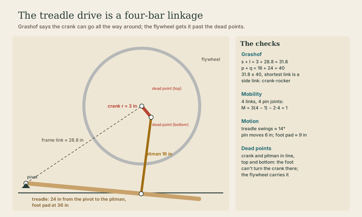
- the frame, fixed: the line from the treadle pivot to the flywheel shaft, about 28.8 inches;
- the crank on the flywheel shaft: 3 inches from shaft to pin;
- the pitman: 16 inches, from the crank pin down to the treadle;
- the treadle: pivoted at the back near the floor, with the pitman attached 24 inches out and the foot pad at 36 inches.
Count the freedom
For a planar linkage, Kutzbach’s equation counts degrees of freedom: M = 3(n − 1) − 2j₁ − j₂, where n is the number of links including the frame, j₁ the one-freedom joints (pins), and j₂ the two-freedom joints. Four links and four pins give M = 3(3) − 8 = 1: one input, the foot, sets the position of everything. It’s a screening count: odd geometry can still bind, which is why the next check matters.
Quick check
One degree of freedom: the foot (or the crank) controls everything.
Is it a crank-rocker?
Grashof’s criterion decides whether any link can turn all the way around. Call the shortest link s, the longest l, and the other two p and q. If s + l ≤ p + q, at least one link rotates fully; which one depends on where the shortest link sits 1:
- shortest link is a side link (pinned to the frame): crank-rocker, with the shortest link as the crank;
- shortest link is the frame: double crank;
- shortest link is the coupler: double rocker;
- s + l > p + q: every link only rocks 1.
Here s = 3 (crank), l = 28.8 (frame), p + q = 16 + 24 = 40. Since 3 + 28.8 = 31.8 ≤ 40 and the crank is pinned to the frame, it’s a crank-rocker: the crank goes all the way around while the treadle rocks. If you’d made the crank 13 inches, the sum would pass 40 and the flywheel could never complete a turn.
Quick check
Shortest plus longest ≤ the other two gives at least one fully rotating link.
Stroke
Solving the geometry through a full turn: the treadle swings about 14°, the pitman pin moves 6 inches up and down (twice the crank), and a foot pad 36 inches from the pivot moves about 9 inches, the stroke in the requirement. A longer crank gives more stroke and more torque per push but a bigger swing; a shorter one, the reverse. The crank length is how you tune it to a leg.
The transmission angle, between the pitman and the treadle, stays between about 78° and 104°, close to the 90° that transmits force best 1. That matters because forces through the pitman act along it; near 90° they turn things instead of just squeezing the pins.
Playback is optional. If the player is unavailable, open the video at its source.
The dead points
Here’s the catch. A crank-rocker is usually driven from the crank. A treadle drives it backward, from the rocker, and that creates dead points: when the crank and pitman line up, at the top and bottom of the crank’s circle, a push from the pitman only squeezes or stretches the crank along its length, and can’t turn it 1. Stop the lathe there and no amount of pushing on the treadle will start it.
There are two standard answers: inertia carries the crank through, or the dead point is avoided by arrangement 1. A treadle lathe uses the first: a heavy flywheel stores enough energy to coast through each dead point and through the cut, and you start it by giving the wheel a pull by hand. The next lesson sizes it.
Quick check
Dead points are where a side link lines up with the coupler.
What to take from this
Write the motion requirement first, then compare mechanisms. The treadle drive is a four-bar with one degree of freedom (Kutzbach M = 1). Grashof (3 + 28.8 ≤ 16 + 24, shortest link a side link) makes it a crank-rocker. The crank length sets the stroke: 3 inches gives a 6-inch pin stroke and about 9 inches at the foot. Driving from the treadle creates two dead points, so the design needs a flywheel.
Lesson complete
Nice work.
Sources for this lesson
- 1Yi Zhang, Susan Finger, Stephannie Behrens. Introduction to Mechanisms, Chapter 5: Planar Linkages. Carnegie Mellon University. verifiedGrashof's criterion: a four-bar has at least one fully rotating link if s + l ≤ p + q (shortest plus longest no more than the other two); if the shortest link is a side link, it's a crank-rocker with the shortest link as the crank; if it's the frame, a double crank; if the coupler, a double rocker; if s + l > p + q, every link rocks. Transmission angle: the angle between coupler and output link; torque transmission is best near 90°. Dead (toggle) points: when a side link lines up with the coupler, torque on the opposite link can't turn it; they're overcome by link inertia (a flywheel) or useful for clamping.
Further reading
- Design and Manufacturing I. MIT OpenCourseWare. verifiedProject-centered course on electromechanical design, machine elements, experiments, drawings, modeling, fabrication, and technical review.