Perception, Localization & Planning
Robot perception as measurement: calibrating cameras and frames, treating detection as a decision with error rates, estimating state with stated uncertainty, layered planning from mission to motion, and closing the loop with evidence.
- 5 min
- 6 steps
- 3 questions
- Lesson 59 of 78
In this lesson
- Calibrate the geometry
- Measure detection as a decision system
- Estimate, do not pretend to know
- Planning layers
- Close the evidence loop
Picking up where you left off.
Perception turns measurements into estimates of objects, obstacles, pose, state, or intent. Planning turns state and goals into actions. Both operate under uncertainty, and neither is complete without a policy for what happens when evidence is weak.
MIT’s robotics material connects sensing, kinematics, planning, and control as one system rather than independent software boxes 1. Stanford’s robotics curriculum similarly treats perception, state estimation, planning, and decision-making as coupled parts of autonomy 2.
Calibrate the geometry
A vision-guided robot needs camera intrinsics, distortion, camera-to-robot transform, tool center point, and part or fixture frame. Calibration residuals should be checked across the working volume. A small image error can become a large depth or pose error depending on geometry.
The ideal pinhole relation illustrates the dependency:
Image coordinates \((u,v)\) depend on focal scale \(f\), lateral position, and depth \(Z\). A one-pixel error therefore does not equal one fixed millimetre everywhere. Lens distortion, imperfect targets, camera focus, thermal drift, mount motion, timestamp error, and hand–eye calibration all enter the final tool-to-part error.
Build a transform chain with named frames and direction arrows. Verify it using independent targets at near, far, center, and edge positions—not only the points used to fit the calibration. Report mean, percentile, and worst-case residuals; a low average can hide a dangerous corner.
Measure detection as a decision system
Accuracy alone is misleading when defects or obstacles are rare. Suppose a test contains 1,000 parts: 80 defective and 920 good. At 95% recall, the system finds 76 defects and misses 4. At a 2% false-positive rate, it rejects about 18 good parts. Precision is then \(76/(76+18)\approx81\%\).
The right threshold depends on consequence and recovery. A missed person is not interchangeable with a false stop; a missed cosmetic defect is not interchangeable with an unnecessary manual check. Use a confusion matrix, precision–recall curve, pose-error distribution, and latency distribution over representative conditions. Calibrate confidence against observed reliability rather than treating the model score as a probability by default.
Estimate, do not pretend to know
Localization combines motion prediction with measurements. A state estimator should carry covariance or at least quality indicators. Wheel slip, reflective surfaces, occlusion, lighting changes, vibration, and moving fixtures violate assumptions. Define conditions under which the estimate is invalid.
For each update, compare the measurement with the predicted observation. A persistently large innovation may indicate a moved camera, wrong data association, encoder fault, or out-of-distribution scene. Covariance that only shrinks while the robot is visibly uncertain signals an overconfident model. Monitor both estimate error and consistency.
State quality should affect behavior. Below one threshold, continue normally; in a caution band, slow down or acquire another view; beyond a rejection threshold, stop, retreat, or ask for help. An explicit abstention state is safer than forcing every frame into a confident label or pose.
Quick check
Estimate, don’t pretend to know.
Planning layers
- Task planning chooses actions and order.
- Path planning chooses collision-free geometry in configuration space.
- Trajectory generation adds time, velocity, acceleration, and jerk limits.
- Control executes while monitoring deviation and disturbances.
A plan must model robot links, tool, payload, fixtures, cable or hose constraints, stopping behavior, and any shared-space rules. “Collision-free points” are not enough if motion between them is unchecked. A path can be geometrically valid but dynamically impossible, singular, too close to obstacles for uncertainty, or unsafe when latency and braking distance are included.
Represent obstacles with appropriate margins for localization error, model error, flex, payload variation, and stopping. More margin is not always the only answer: a better view, slower speed, alternate grasp, or fixture change can reduce uncertainty at its source.
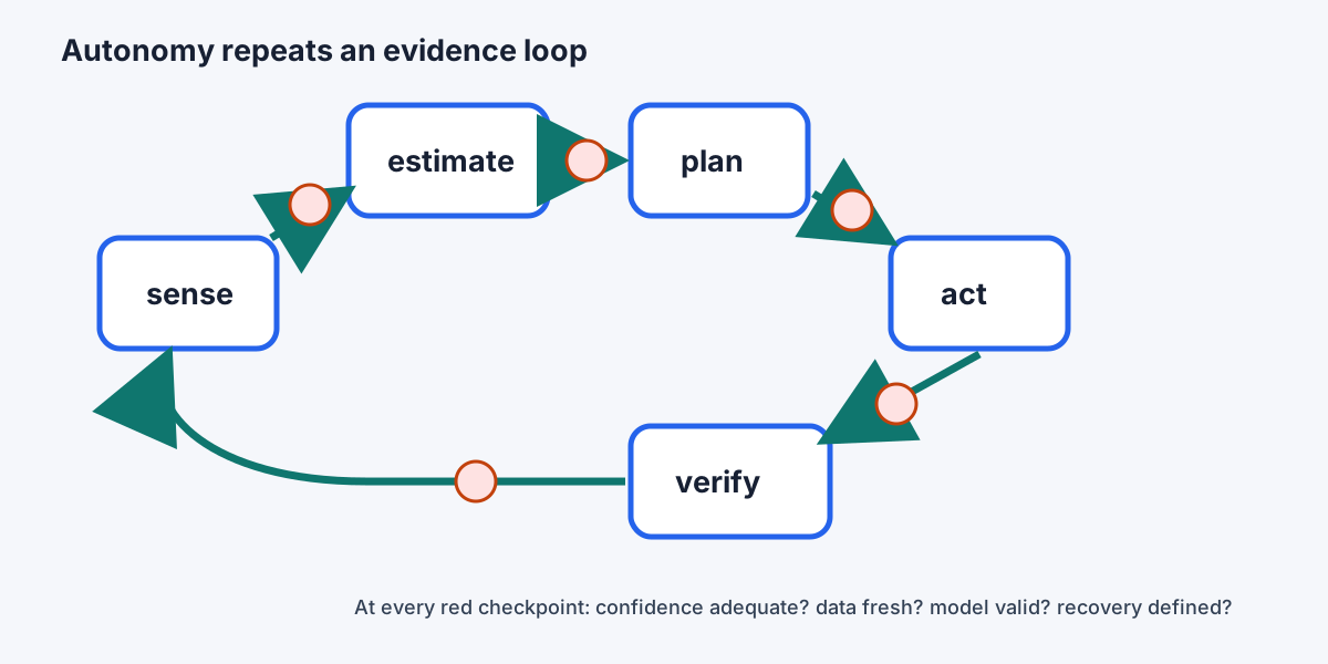
Close the evidence loop
After acting, verify the expected state: part acquired, fixture clear, pose within tolerance, insertion complete, downstream ready. Open-loop assumption chains make a single missed detection propagate into damage. Timeouts and retries need bounds; repeating the same failed action without new information is not recovery.
Design a recovery ladder: reacquire from another view, re-localize against a trusted reference, move to a known safe pose, route the part to manual review, or enter a controlled stop. Log the image or sensor slice, estimate, confidence, chosen plan, controller result, and recovery so failures can be reconstructed.
Stanford’s collaborative-robotics work emphasizes that shared autonomy also needs interpretable intent, human-aware motion, and clear allocation of authority 3. A technically feasible path can still be startling or ambiguous to a nearby person. Predictability is part of system performance.
Perception and planning test set
Create a matrix over lighting, part color, orientation, occlusion, background, camera contamination, vibration, incorrect parts, calibration age, and network or compute load. Record false positive, false negative, pose error, latency, confidence calibration, planner failure, clearance, and recovery result. Reserve cases for final evaluation rather than tuning on every example.
Define acceptance in operational terms: for example, “miss no more than one defect in 500 at the specified defect set; 99.5% of accepted pose errors below 0.6 mm; decision latency below 120 ms at the 99th percentile; every no-path condition reaches a safe state.” Then test shifts deliberately—new supplier finish, aged lighting, moved fixture, partial obstruction—and confirm the system detects when it has left its validated envelope.
Practice
A confidence score must be related to observed reliability and an operational decision threshold.
Practice
Planning failure is an expected state that needs bounded handling.
Lesson complete
Nice work.
Sources for this lesson
- 1Introduction to Robotics. MIT OpenCourseWare. verifiedMechanisms, kinematics, planning, dynamics, controls, actuators, sensors, networks, interfaces, embedded software, laboratories, and a team robot project. Cited at: robot sensing and control.
- 2CS223A / ME320 - Introduction to Robotics. Stanford University. verifiedCurrent physics-based syllabus covering spatial transformations, kinematics, Jacobians, dynamics, motion and force control, and vision-based control. Cited at: robot perception and planning.
- 3Collaborative Robotics. Stanford University. verifiedProject-based course on task objectives, perception, control, teammate modeling, communication, consensus, and human-robot collaboration. Cited at: human–robot collaboration.