Frames, Transforms & Forward Kinematics
Coordinate frames and homogeneous transforms, composing them by their labels, forward kinematics for a planar two-link arm with a worked example, and treating every frame in a robot cell as a calibrated engineering interface.
- 2 min
- 4 steps
- 3 questions
- Lesson 55 of 78
In this lesson
- Pose as rotation plus translation
- Planar two-link arm
- Frames are engineering interfaces
Open alongside this lesson
-
Stanford Engineering Everywhere - CS223A Introduction to Robotics (opens in a new tab)
Use the spatial-description and forward-kinematics sessions after this lesson.
-
Introduction to Robotics (opens in a new tab)
Compare MIT's integrated project structure with the capstone later in this path.
Picking up where you left off.
Robots reason in coordinate frames. Stanford CS223A begins with spatial descriptions before forward kinematics, Jacobians, inverse kinematics, dynamics, and control 1.
Playback is optional. If the player is unavailable, open the video at its source.
Pose as rotation plus translation
A homogeneous transform from frame B to frame A is
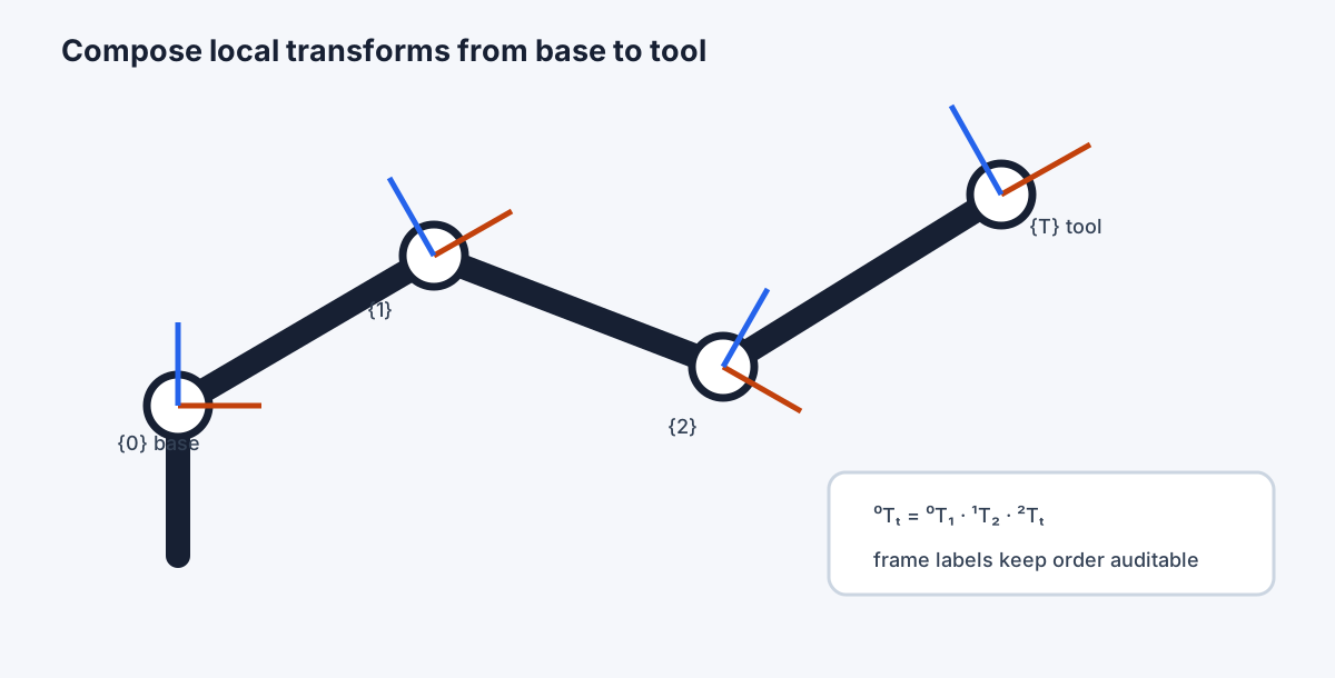
It maps coordinates expressed in B into A. Composition follows the frame labels:
Matrix order matters because rotations generally do not commute. Write superscripts and subscripts until the chain cancels cleanly.
Planar two-link arm
For link lengths \(l_1,l_2\) and revolute joints \(q_1,q_2\), tool position is
With \(l_1=0.40\) m, \(l_2=0.30\) m, \(q_1=30^\circ\), and \(q_2=45^\circ\), \(x\approx0.424\) m and \(y\approx0.490\) m. Check the result against maximum reach 0.70 m and a sketch of the quadrant.
Quick check
x = 0.40 cos 30° + 0.30 cos 75°, y = 0.40 sin 30° + 0.30 sin 75°; the reach limit is 0.70 m.
Frames are engineering interfaces
Define base, world, fixture, part, camera, flange, tool, and task frames. Record who establishes each, how it is calibrated, when it can change, and what invalidates it. Many “robot accuracy” problems are actually loose fixtures, wrong tool-center-point data, or stale frame calibration.
Frame audit
Sketch a pick-and-place cell with every coordinate frame and transform. For each, label fixed by design, measured during setup, or estimated during operation. Then trace one point from camera pixels to part pose to robot base to tool command. Every unstated transform is a future integration defect.
Practice
A 4 by 4 homogeneous transform combines orientation and position in one composable mapping.
Practice
Forward kinematics maps configuration to pose; inverse kinematics reverses that question.
Lesson complete
Nice work.
Sources for this lesson
- 1CS223A / ME320 - Introduction to Robotics. Stanford University. verifiedCurrent physics-based syllabus covering spatial transformations, kinematics, Jacobians, dynamics, motion and force control, and vision-based control. Cited at: 2026 syllabus.
Further reading
- Introduction to Robotics. MIT OpenCourseWare. verifiedMechanisms, kinematics, planning, dynamics, controls, actuators, sensors, networks, interfaces, embedded software, laboratories, and a team robot project.
- Stanford Engineering Everywhere - CS223A Introduction to Robotics. Stanford University. verifiedFree lecture videos, transcripts, handouts, and assignments on robot kinematics, Jacobians, planning, dynamics, and control.
- Introduction to Robotics at MIT. MIT Department of Mechanical Engineering. 2015. verifiedOfficial MIT MechE video showing the 2.12 project model and its integration of design, manufacturing, controls, programming, and teamwork.