Conveyors, Pneumatics & Equipment Handshakes
Moving a part from one machine to the next: a ready-request-confirm handshake between the infeed conveyor and the drill station, with a signal table and what happens when a step never finishes. Conveyor zones and why throughput depends on spacing, not belt speed. Air cylinders: force from pressure times area (worked), speed from meter-out flow controls, what the valve does when power drops, and bleeding trapped air before anyone reaches in.
- 6 min
- 6 steps
- 3 questions
- Lesson 63 of 78
In this lesson
- Who owns the part
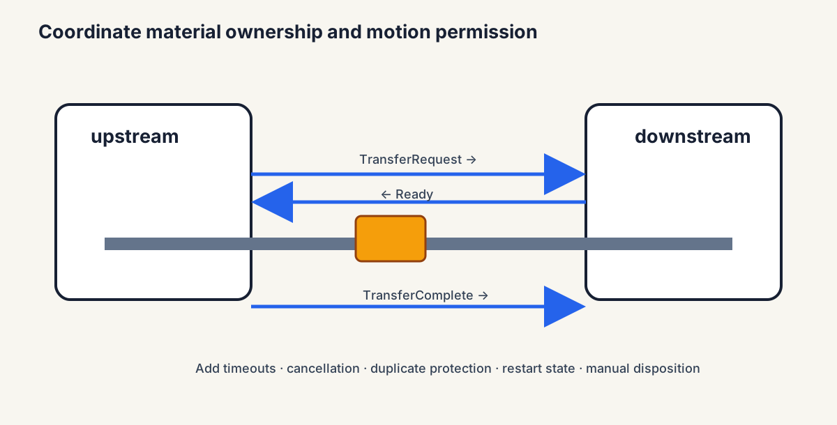
- A transfer handshake
- Conveyor zones
- Air cylinders
- When the power or air goes
- Try it
Picking up where you left off.
Who owns the part
A cell is a chain of machines handing parts to each other. Every handoff has to answer three questions: who owns the part right now, who is allowed to move, and what counts as done. Get those wrong and you get two machines moving at once, a part crushed between them, or a part that vanishes from the tracking while it sits physically in the station.
The answer is a handshake: a few signals passed between the two controllers in a fixed order, each with a meaning, a rule for turning it on, a rule for turning it off, and a timeout.
A transfer handshake
Infeed conveyor to drill station, one bracket at a time:
| # | Signal | From → To | Means | Turns off when |
|---|---|---|---|---|
| 1 | Station_Ready |
drill → conveyor | station is empty, in auto, no fault | the part arrives |
| 2 | Part_Available |
conveyor → drill | a part is waiting at the end of the belt | the part leaves the belt |
| 3 | (conveyor runs) | — | both 1 and 2 are on, so the conveyor indexes | part leaves the belt |
| 4 | Part_Left |
conveyor’s end photoeye | the part is gone from the belt | — |
| 5 | Part_Arrived |
drill’s stop photoeye | the part is at the stop | the part is removed |
Ownership moves to the drill station only when its photoeye sees the part. The conveyor clears its signals only when its photoeye sees the part gone. Neither trusts the other’s command bit as proof.
Then the abnormal cases, which are where the real design work is:
- The part leaves the belt but never arrives (it fell off, or jammed in the transfer): after a travel timeout, say 3 seconds, both sides fault, and the alarm says “part lost between conveyor and drill station.”
- Power cycles mid-transfer: on restart, each side reads its own sensors and asks the operator to confirm where the part is, rather than guessing.
- Someone removes a part by hand: the station sees its stop sensor go dark without a completed cycle and flags the part as unprocessed.
Quick check
Each machine updates who owns the part only after its own sensor confirms it.
Conveyor zones
A conveyor is usually split into zones, each with its own photoeye and drive or brake, so parts can wait in a line without pushing on each other (zero-pressure accumulation). A zone runs only when the zone ahead is empty.
Throughput isn’t belt speed. If the drill station takes 20 seconds per bracket, the cell makes three brackets a minute no matter how fast the belt runs; a faster belt only fills the queue sooner. What the belt does need is to deliver the next part in less time than the station takes to finish the current one, plus a few parts of buffer so a short stoppage upstream doesn’t starve the station. More on that in the throughput lesson.
Conveyors also have their own hazards: in-running nip points where belts wrap pulleys, and jams that people clear by hand. Guard the nip points, and put jam access where it can be reached with the conveyor locked out 1.
Air cylinders
The clamp at the drill station is an air cylinder. Three numbers matter.
Force. Force equals pressure times piston area. A 2-inch bore has an area of π × 1² = 3.14 in²; at 80 psi it pushes about 250 lb extending. Retracting, the rod takes up part of the area: with a 5/8-inch rod (0.31 in²) the retract area is 2.83 in², about 226 lb. Size the cylinder so it clamps hard enough at the lowest pressure the plant air ever drops to, and regulate it down if full pressure would mark or bend the part.
Speed. Cylinders are slowed with flow controls, usually meter-out: restricting the air leaving the cylinder, which holds the piston steadier than restricting the air going in. End-of-stroke cushions keep it from slamming.
Proof. A reed switch on the cylinder says the piston reached the end of its stroke. It doesn’t prove the clamp is gripping the part hard enough. If clamp force matters, add a pressure switch on the clamp side and check both.
Quick check
Retracting it pushes less, because the rod takes up part of the piston area.
When the power or air goes
Decide what each valve does when its solenoid loses power:
- A spring-return valve goes back to its home position: the clamp opens. Good for most motions; bad if an open clamp drops a heavy part.
- A detented (two-solenoid) valve stays where it was.
- A center-blocked three-position valve traps air in both ends, holding the cylinder where it is.
That trapped air is stored energy. A clamp held closed by blocked air can snap open or shut when someone loosens a fitting. OSHA’s lockout/tagout rule covers pneumatic and other stored energy, not just electricity: before service, the air supply is locked out and the trapped air is bled off so nothing can move 1. Build the machine with a lockable dump valve and bleed points so that’s easy to do.
Quick check
OSHA’s lockout rule covers stored pneumatic energy, not just electricity.
Try it
Write the full signal table for the drill station handing finished brackets to the robot: who asserts each signal, what turns it off, the timeout, and what each side does when the timeout trips. Then size the clamp cylinder for a 150 lb clamp force when plant air sags to 60 psi.
Lesson complete
Nice work.
Sources for this lesson
- 129 CFR 1910.147 - The Control of Hazardous Energy (Lockout/Tagout). Occupational Safety and Health Administration. verifiedU.S. general-industry minimum performance requirements for controlling unexpected energization, startup, and release of stored energy during service and maintenance. Cited at: hazardous energy scope.
Further reading
- OSHA Technical Manual, Section IV, Chapter 4 - Industrial Robot Systems and Industrial Robot System Safety. Occupational Safety and Health Administration. 2021. verifiedRobot-system components, lifecycle hazards, risk assessment, safeguards, collaborative modes, training, evaluation, and applicable U.S. requirements.
- Design and Manufacturing II. MIT OpenCourseWare. verifiedModern manufacturing organized around process physics, equipment and control, manufacturing systems, and design for manufacture.