Mechanical, Electrical & Control Design Package
Detailed design of the automatic dust collection: sizing the gate actuator from measured slide force (a 180° servo's stroke is twice its arm, so torque grows with stroke), picking a current-transformer burden resistor for the real tool current instead of the CT's rating, clipping it around one conductor, keeping line voltage inside a listed motor-rated relay, and a state machine with timeouts, hysteresis, a make-before-break bleed-gate rule, and safe power-up. Ends with an interface review that walks every boundary.
- 7 min
- 6 steps
- 3 questions
- Lesson 75 of 78
In this lesson
- Three views of one design
- Mechanical: the gate actuator
- Electrical: sensing the tool
- Control: the state machine
- Interface review
Picking up where you left off.
Three views of one design
Detailed design is a set of coordinated views, each answering different questions:
- Mechanical: what moves the gate, how far, with what force, and how it mounts to the duct.
- Electrical: how the controller knows a tool is running, how it switches the collector, and where line voltage stops and low voltage begins.
- Control: what the controller does in every situation, including the bad ones.
Each view gets its own sketch and calculations; the interface review at the end checks that they agree.
Mechanical: the gate actuator
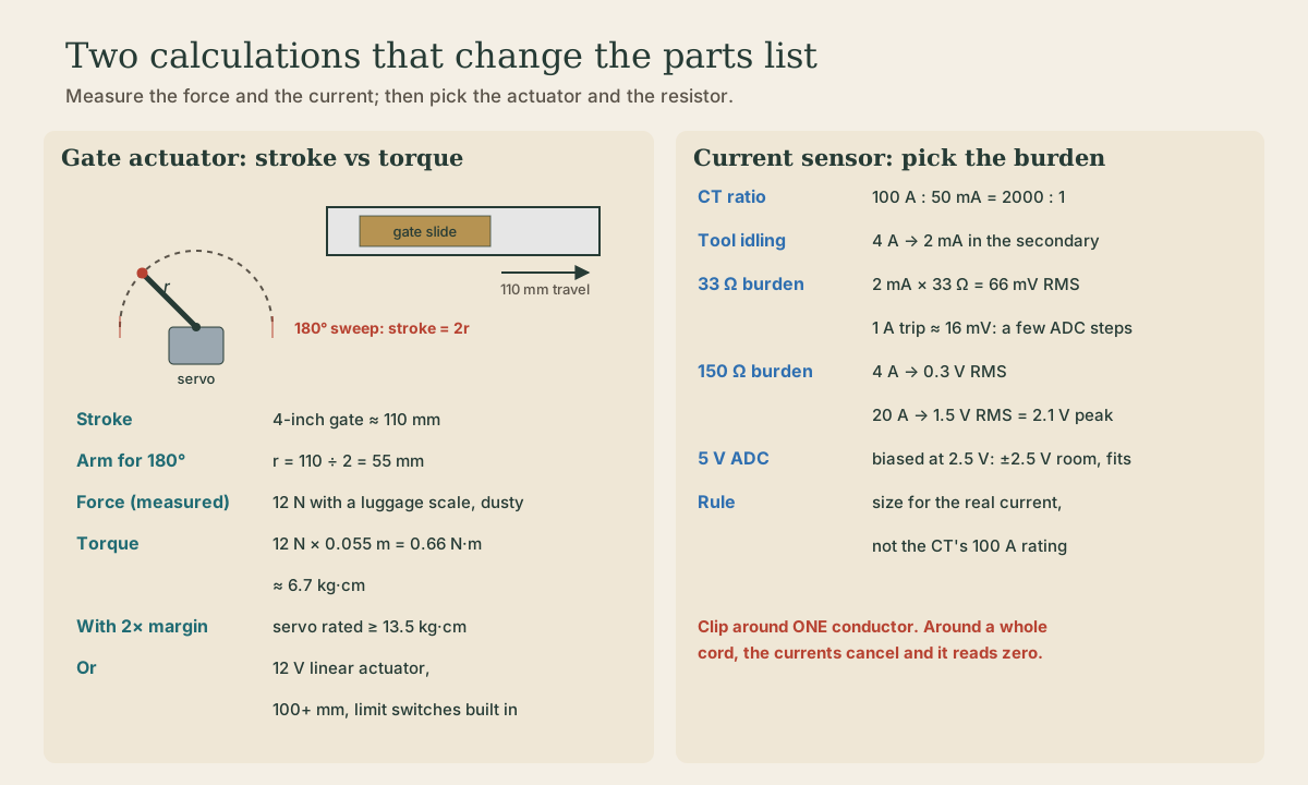
A 4-inch blast gate’s slide travels about 110 mm from closed to fully open. First, measure the force: hook a luggage scale to a slide that’s seen some dust and pull it open. Suppose it reads 12 N. Don’t guess this number; dust and pitch make old gates stiff.
A hobby servo turns about 180°. A pin on its arm moves through a semicircle, and the straight-line distance it covers is the chord, 2r. To get 110 mm of stroke the arm must be r = 55 mm. The torque needed is then
With a 2× margin for a stickier gate and a weaker battery day, look for a servo whose datasheet stall torque is at least 13.5 kg·cm, and use a linkage so the slide isn’t pushed sideways. The alternative is a 12 V linear actuator with at least 100 mm of stroke and built-in limit switches: more expensive, simpler to mount, and it holds position without power. Either way, add a limit switch that closes only when the gate is fully open. The controller trusts the switch, not the command.
Quick check
12 N × 0.055 m = 0.66 N·m; a short arm would need less torque but couldn’t reach.
Electrical: sensing the tool
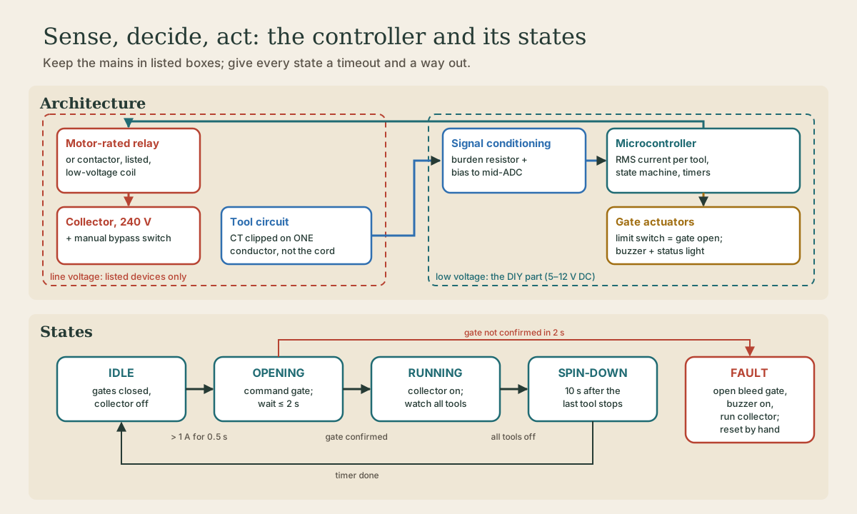
A current transformer (CT) measures alternating current in a wire passed through its core. A split-core CT clips on without disconnecting anything, but it must go around one conductor, the live or the neutral, not both 1. Around a whole cord, the outgoing and returning currents cancel and it reads nothing. So each CT goes inside the box that feeds the tool’s receptacle, around one hot conductor, with the box closed up again. On a 240 V tool, clip one of the two hots. In Wisconsin an owner-occupant can do that wiring in their own home, and it still has to meet code 2.
The CT puts out a small current. A burden resistor turns it into a voltage, and a bias network centers it at half the microcontroller’s analog range so the AC swing stays positive 1. The resistor value is a real design decision:
- A common split-core CT is 100 A : 50 mA, a 2000 : 1 ratio. Measure each tool’s no-load running current with a clamp meter; suppose the saw idles at 4 A. That’s 2 mA in the CT’s secondary.
- With a 33 Ω burden (a common choice for measuring a whole house at up to 100 A), 2 mA gives only 66 mV RMS. At a 1 A threshold it’s about 16 mV, a few steps of a 10-bit converter on 5 V. Low currents use very few ADC steps 1, so that’s marginal.
- With 150 Ω, 4 A gives 0.3 V RMS, and 20 A gives 1.5 V RMS (2.1 V peak), still inside the ±2.5 V available around a 2.5 V bias.
So size the burden for the real current, not the CT’s 100 A rating. A motor’s starting inrush will briefly overdrive the input; a series resistor ahead of the pin keeps that within its limits, and for on/off detection a moment of clipping doesn’t matter.
Quick check
Clip it around one conductor only: the live or the neutral, not both.
The line-voltage boundary
The controller never switches the collector motor directly. Its output drives the low-voltage coil of a listed relay or contactor whose contacts are rated for the collector motor’s horsepower and voltage (read the motor nameplate). A manual switch wired as a bypass runs the collector with the controller unplugged. Everything the hobby electronics touch is 5 to 12 V DC.
Playback is optional. If the player is unavailable, open the video at its source.
Control: the state machine
Write the controller as a state machine. IEC 61131-3’s sequential function charts and structured text exist to make exactly this kind of behavior readable 3, and the same structure works in any language.
- IDLE: all tool gates closed, bleed gate open, collector off.
- OPENING: a tool’s current has been over its threshold for 0.5 s. Command its gate open; wait up to 2 s for the limit switch.
- RUNNING: gate confirmed. Close the bleed gate, start the collector. If a second tool starts, open its gate too. If one of two stops, close its gate.
- SPIN-DOWN: the last tool has been under threshold for 1 s. Keep the collector and gate as they are for 10 s to clear the duct, then open the bleed gate, stop the collector, and close the tool gate.
- FAULT: a gate didn’t confirm in 2 s. Open the bleed gate, sound the buzzer, and run the collector anyway so the cut isn’t made with no collection. Clear it only by hand once the cause is found.
Three rules make it safe:
- Make before break. The bleed gate closes only after a tool gate confirms open, and opens before the last tool gate closes. The collector can never pull against all-closed gates 4.
- Hysteresis. Turn on above about half the tool’s measured idle current, and off below a lower value for a full second, so a motor coasting down doesn’t toggle the collector.
- Safe power-up. After any reset or power blip the controller starts in IDLE with the bleed gate open and the collector off, whatever it was doing before.
Quick check
Make before break: a tool gate confirms open before the bleed closes, and the bleed opens before the last tool gate closes.
Interface review
Walk every boundary between views and ask:
- Does the actuator’s stroke match the slide’s travel, and does the limit switch trip only at fully open?
- Is each tool’s idle current comfortably above its threshold, and is every other circuit’s load invisible to its CT?
- Is the relay’s horsepower rating at least the collector motor’s, and does the manual bypass work with the controller unplugged?
- What does each actuator do when power is lost: stay put, or spring closed? Does that ever leave all gates closed while the collector coasts?
- Can the controller box, actuators, and limit switches be reached for service without taking down duct?
Gate 3
Pass when every requirement from the matrix traces to a design feature or calculation, the measured gate force and idle currents are in the notebook, the line-voltage parts are chosen and listed, and the state machine has a timeout and a way out of every state.
Lesson complete
Nice work.
Sources for this lesson
- 1CT Sensors: An Introduction and Interfacing with an Arduino. OpenEnergyMonitor. verifiedA current transformer measures alternating current in a conductor passed through its core; a split-core CT clips on without high-voltage work, around the live OR the neutral conductor, not both. The secondary current is turned into a voltage by a burden resistor and biased to the middle of the microcontroller's ADC range; low currents use only a few ADC steps, so resolution limits small-load sensing.
- 2Wis. Stat. 101.862, Electrician licensing. Wisconsin Legislature. verifiedElectrical wiring generally requires licensed or registered electricians under a master electrician; subsection (4)(a) exempts a residential property owner who installs, repairs, or maintains wiring on premises the owner owns and occupies as a residence, unless a local ordinance requires a license or registration; (4)(d) exempts systems of 100 volts or less.
- 3IEC 61131-3:2025 - Programmable Controllers, Part 3: Programming Languages. International Electrotechnical Commission. 2025. verifiedCurrent syntax and semantics for structured text, ladder diagram, function block diagram, and sequential function chart organization.
- 4Bill Pentz. Dust Collection Ducting. Bill Pentz Cyclone and Dust Collection Research. verifiedSmall-shop stationary tools need about 350 CFM to collect visible chips and about 1000 CFM for good fine-dust collection. Design air speed about 4000 FPM in vertical runs and 3000 FPM in horizontal runs (3800 minimum vertical, 2800 horizontal; 4500 for large chips). A 1.5 hp collector rated 1100 CFM maximum actually moves about 785 CFM through 6-inch duct, 550 through 5-inch, and 350 through 4-inch. Doubling airflow takes about four times the static pressure and much more horsepower. Thin 30-gauge duct can collapse if the system starts with no blast gates open. Static charge on PVC can shock you but experts find it insufficient to cause an explosion in hobby systems.
Previous: Requirements, Architecture Options & Concept Review