Pumps, Pressure Tanks, and Compressed Air
A private well system as an operating-point problem: submersible, jet, and centrifugal pumps; the pump curve crossing the system curve (lift plus tank pressure at 2.31 ft per psi plus friction), and why flow drops as the tank fills from 40 to 60 psi; a bladder tank's drawdown by Boyle's law (about 11 gallons from a 44-gallon tank); constant-pressure VFD pumps; then the shop compressor: 7 to 8 hp of electricity per air-motor horsepower, the on/off leak test, and the cost of running pressure higher than you need.
- 8 min
- 7 steps
- 4 questions
- Lesson 42 of 78
In this lesson
- The pumps
- The operating point
- Why a 44-gallon tank holds 11 gallons
- Compressed air
- Try it
Picking up where you left off.
A pump doesn’t decide on its own how much it delivers. It hands over flow at whatever pressure the pipes push back with, and the pipes decide how hard they push back. Where those two meet is the operating point, and nearly every pump, fan, or blower problem comes down to finding it. A private well system shows it clearly, and a shop compressor shows what pumping a gas costs.
The pumps
From the Nebraska Extension guide to private well systems 1:
- Submersible pump. Pump and motor in one long unit about 3½ inches across, hung below the water level in a drilled well (casing at least 4 inches). There’s nothing above ground to freeze, but the pump has to be pulled from the well for repair. This is the common choice for drilled wells.
- Jet pump. Above ground, for water less than 25 feet down (shallow-well) or 25 to 250 feet with the jet down in the well (deep-well). It must be primed, and an air leak in the suction line loses the prime.
- Centrifugal pump. A spinning impeller speeds the water up and a diffuser turns that speed into pressure. It can lift by suction no more than 25 feet, and it makes a good booster.
The 25-foot suction limit is physics, not a design shortcoming. A pump can’t pull water up; it can only lower the pressure above the water and let the atmosphere push it up. Atmospheric pressure at sea level holds up about 34 feet of water in a perfect vacuum, and real pumps get to around 25.
The operating point
Head is pressure expressed as a height of water: 1 psi = 2.31 ft 1. Measuring everything in feet lets lift and pressure add directly.
The system curve is the head the plumbing demands at each flow rate:
system head = lift + tank pressure × 2.31 + friction
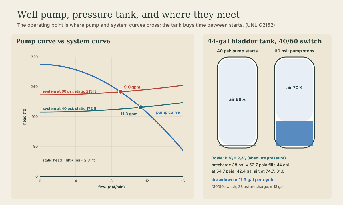
The first two terms are fixed; friction grows with flow (see the barn pipeline lesson). The pump curve, from the manufacturer, falls the other way: a centrifugal pump makes its highest head at zero flow and less head as flow rises. The pump runs where the curves cross 2.
Example: the pumping water level is 80 ft down, and the pump sits under a 40/60 switch.
- At 40 psi, static head = 80 + 40 × 2.31 ≈ 172 ft. The curves cross near 11.3 gpm.
- At 60 psi, static head = 80 + 60 × 2.31 ≈ 219 ft. The crossing slides to about 9 gpm.
So the pump delivers less and less as the tank fills. That matters when you’re filling a stock tank: the flow you measured right after the pump kicked on isn’t what you get near cut-out. And if the water table drops in a drought, the whole system curve moves up and the flow drops again.
Playback is optional. If the player is unavailable, open the video at its source.
Quick check
80 ft + 50 psi × 2.31 ft/psi ≈ 80 + 116 = 196 ft.
Quick check
A centrifugal pump trades flow for head along its curve.
Why a 44-gallon tank holds 11 gallons
The pressure tank has three jobs: deliver water under pressure while the pump is off, cut down how often the pump starts (starting is the hardest part of a pump motor’s life), and cover short bursts of high demand 1. It works because water doesn’t compress and air does. In a modern bladder tank, water fills a rubber bladder that squeezes a sealed air charge 1.
How much water it actually delivers comes from Boyle’s law: at constant temperature, pressure × volume stays constant for a trapped gas, using absolute pressure (gauge pressure + 14.7 psi) 3.
A 44-gallon tank, precharged with air to 38 psi (2 psi under cut-in), on a 40/60 switch:
- Empty of water, the air fills all 44 gal at 38 + 14.7 = 52.7 psia.
- At cut-in, 40 psi (54.7 psia): air = 44 × 52.7 / 54.7 ≈ 42.4 gal.
- At cut-out, 60 psi (74.7 psia): air = 44 × 52.7 / 74.7 ≈ 31.0 gal.
Water delivered between pump starts = 42.4 − 31.0 ≈ 11.3 gallons. On a 30/50 switch with a 28 psi precharge the same tank gives about 13 gallons, which is why higher switch settings call for bigger tanks.
If the precharge leaks down, the bladder takes more water, the air cushion shrinks, and the pump starts to short-cycle, kicking on every time a faucet opens. Checking the precharge with the system drained, using a tire gauge on the tank’s air valve, is basic well maintenance. Old galvanized tanks without bladders absorb their air into the water and waterlog the same way 1.
Playback is optional. If the player is unavailable, open the video at its source.
The tank’s low pressure also has to satisfy the house. The Nebraska guide notes that water softeners, washing machines, and dishwashers need at least 30 psi 1. A long uphill line to an outbuilding has to hold that at cut-in, too.
Quick check
Boyle’s law in absolute pressure: air goes from 42.4 to 31.0 gallons, freeing about 11.3 gallons for water.
Constant-pressure pumps
A variable-frequency drive changes the pump’s speed instead of switching it on and off: open a faucet, pressure dips, and the pump speeds up just enough to hold it. These systems need only a 1–2 gallon tank, start the motor far less often, and use less energy 1. In curve terms, slowing the pump shrinks its whole curve until it crosses the system curve exactly at the pressure you set.
Compressed air
A compressor is a pump for a gas, and gas fights back differently: compressing it makes it hot, and that heat is thrown away as the tank cools. By the time leaks, pressure drops, and the tool’s own losses are added, the DOE’s compressed-air sourcebook figures an air motor needs at least 7 to 8 hp at the compressor for every 1 hp it delivers 4. Air is a convenient way to power tools, but an expensive one.
The leak test
Leaks are the most common waste. Badly maintained systems lose 20–30% of the compressor’s output to them, and under 10% is a well-kept system 4. For a compressor with start/stop control, which covers nearly every shop compressor, you can measure it with a stopwatch 4:
- Bring the system up to pressure with every tool and valve closed.
- Time how long the compressor runs (T) and how long it sits off (t), over several cycles.
- Leakage (%) = T × 100 / (T + t).
Running 1.5 minutes and resting 6 means 1.5 × 100 / 7.5 = 20%: a fifth of the electricity is going out through leaks. Find them with soapy water brushed on couplings, hose ends, regulators, the tank drain, and threaded joints, which is where most leaks are 4.
Pressure costs too
Every psi above what the tools need makes the compressor work harder and pushes more air out every leak. In industrial systems near 100 psi, the sourcebook puts the cost at about 1.6–2% more energy for every 2 psi of extra pressure 4. Set the regulator to what the tool actually needs, not to the tank’s maximum.
Quick check
Leakage % = T × 100 / (T + t) = 1.5 × 100 / 7.5 = 20%. Under 10% is good.
Try it
Do the leak test on your compressor tonight, all tools off. Then, if you have a well, find the pump’s switch settings, drain the tank, and check its precharge. Is it 2 psi under cut-in? Count how many gallons come out of a faucet between pump starts and compare with the Boyle’s-law figure for your tank size.
Lesson complete
Nice work.
Sources for this lesson
- 1Private Drinking Water Wells: The Distribution System (G2152). University of Nebraska-Lincoln Extension. 2012. verifiedSubmersible pumps (about 3.5 in diameter, below water level, need 4-in casing); shallow jet pumps under 25 ft, deep jet 25-250 ft, must be primed; centrifugal suction lift max 25 ft; VFD constant-pressure systems use small 1-2 gal tanks and fewer starts; pressure switch is the brain; tank stores water, cuts pump starts, supplies peaks; pump typically stops at 40-60 psi and starts at 20-40 psi; softeners, washers, dishwashers need at least 30 psi; bladder and diaphragm tanks since 1970; galvanized tanks waterlog.
- 2Fluid Dynamics. MIT OpenCourseWare. verifiedUndergraduate course on pressure, control volumes, conservation laws, pipe flow, dimensional analysis, boundary layers, lift, and drag.
- 3University Physics, Volumes 1–3. OpenStax (Rice University). verifiedOpen calculus-based physics. Vol 1 mechanics; Vol 2 thermodynamics and electricity & magnetism; Vol 3 optics & modern physics.
- 4Improving Compressed Air System Performance: A Sourcebook for Industry (3rd ed.) and Fact Sheet 7, Compressed Air System Leaks. U.S. Department of Energy and Compressed Air Challenge. 2016. verifiedAir motors need a minimum of 7 to 8 hp of compressor power per hp of shaft output; pneumatic tools cost 7-8 times the energy of electric tools for the same output. Fact sheet 7 (2026 rev.): leaks can waste 20-30% of output, well maintained under 10%; for start/stop compressors, leakage % = T x 100 / (T + t) with on-load time T and off-load time t, measured with all tools off; find leaks with ultrasonic detectors or soapy water; most leaks at couplings, hoses, fittings, regulators, traps, thread sealant. Raising header pressure 2 psi raises energy use about 1.6-2% in systems near 100 psig.