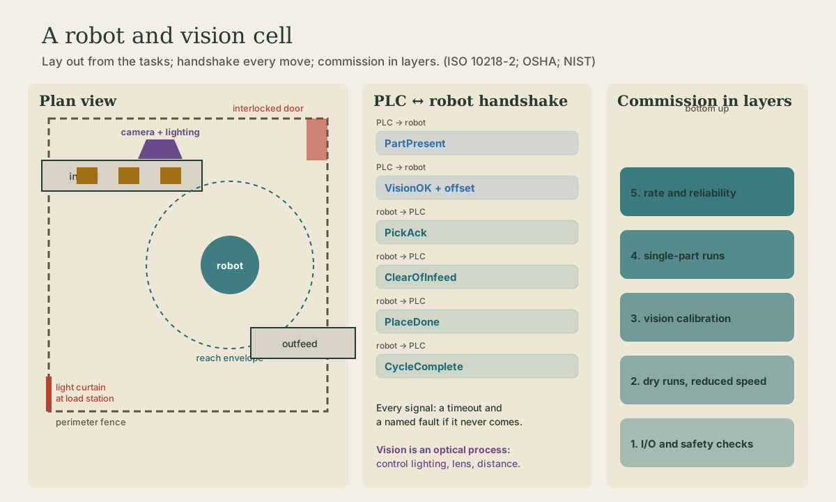
Robot, Vision & Cell Integration
Putting a robot into the drill cell: when robot accidents actually happen (setup, programming, and maintenance, not normal running), the safeguards OSHA describes (fences, interlocked gates, light curtains, mats, teach-mode speed of 250 mm/s with a three-position enabling switch, and the four collaborative modes), a camera that finds the bracket and the error budget behind it, splitting the job between the PLC and the robot controller, and commissioning one layer at a time.
- 6 min
- 7 steps
- 3 questions
- Lesson 64 of 78
In this lesson
- The job
- When people get hurt
- Safeguarding the cell
- A camera to find the part
- PLC and robot: who does what
- Commission one layer at a time
- Try it
Picking up where you left off.
The job
Back to the drill cell: brackets come down the infeed conveyor at slightly different angles, a camera finds each one, the robot picks it and loads the drill fixture, then later unloads the finished part to the outfeed. ISO 10218-2 treats the whole robot application, not just the arm, as the thing to be designed and made safe: the robot, its gripper, the fixtures, the conveyors, the controls, the safeguards, and the people who work around it, from installation to disposal 1.
When people get hurt
OSHA’s technical manual notes that studies in Sweden and Japan found many robot accidents don’t happen during normal operation. They happen during assembly, installation, programming, testing, and maintenance, when people are first exposed to the robot’s motion 2. OSHA’s case examples are telling: a programmer struck by a move they didn’t expect; a worker pinned between the arm and a post after walking through an inadequate perimeter; a mechanic struck when a coworker switched power back on; a worker hit after reaching in to clean a sensor while the robot was in automatic 2.
The hazards are impact (being struck), crushing and trapping between the arm and something fixed, parts or tools thrown by a mechanical failure, and the electrical, hydraulic, and pneumatic energy that drives it all 2.
Quick check
That’s why teach-mode speed limits, enabling switches, and lockout matter as much as fences.
Safeguarding the cell
OSHA describes these safeguards 2:
- Fixed fences around the robot’s restricted space, tall enough and far enough out that no one can reach in.
- Interlocked gates: opening the door stops the robot through the safety circuit.
- Presence-sensing devices: light curtains across the openings where parts come in and out, safety mats, and area laser scanners.
- Limiting devices that restrict how far the arm can travel.
- Teach mode: when someone programs with the pendant inside the cell, the robot moves at 250 mm/s (10 in/s) or less, and only while they hold a three-position enabling switch in its middle position. Let go or squeeze it hard in a panic and motion stops.
Collaborative operation, where a person and robot share space, uses one of four methods: safety-rated monitored stop (the robot stops and holds while the person is in), hand guiding, speed and separation monitoring (the robot slows and stops as a person gets closer), or power and force limiting (contact is allowed but the forces are kept low enough not to injure) 2. A small arm doesn’t make an application collaborative; a sharp gripper or a heavy steel bracket can still hurt.
All of this runs through safety-rated controls, not the ordinary PLC program.
Quick check
Releasing or squeezing the enabling switch past its middle position stops motion.
A camera to find the part
Machine vision works best when you control the scene before you write software:
- Lighting: a backlight under a translucent belt section makes the bracket a sharp black silhouette, immune to shop lights and oil sheen.
- Field of view and resolution: to locate a 150 mm bracket within 0.5 mm, a camera with 1,600 pixels across a 200 mm field gives about 0.125 mm per pixel, enough margin for edge-finding.
- Trigger: take the picture when the part is stopped, or strobe the light, so motion doesn’t blur it.
Then the error budget. A missed pick could come from any link: how well the software finds the edges, the camera calibration (lens distortion, scale), the camera-to-robot calibration (where the camera’s picture sits in the robot’s coordinates), the tool center point (where the robot thinks the gripper fingers are), part and fixture variation, and the robot’s own repeatability. Measure each one separately. If you don’t, you’ll spend a week re-teaching points to fix what was really a bumped camera bracket.
Quick check
Measure each error source separately, or you’ll fix the wrong one.
PLC and robot: who does what
The usual split: the PLC runs the cell sequence and the equipment (conveyors, clamp, drill, safety status), and the robot controller runs the robot’s motion. They talk through a handshake like the one in the last lesson:
- PLC → robot:
Job_Number(which program),Start,Fixture_Clear,Reset. - Robot → PLC:
Ready,Busy,At_Home,In_Fixture_Zone,Gripper_Closed,Complete,Fault.
Two rules: start motion on a held signal, not a single-scan pulse that can be missed; and have the robot echo back the job number before it moves, so it never runs the wrong program for the part in front of it. And the PLC never lets the drill clamp close while the robot reports In_Fixture_Zone.
Commission one layer at a time
Bring the cell up in layers, so each problem shows up alone: wiring and I/O checks; robot frames and tool center point; paths run slowly with no part; gripper and fixtures; sensors and handshakes; the process itself; every fault case; and finally full-rate runs with real part variation. NIST’s work on robot performance measures exists so integrators and buyers can agree on what “working” means with numbers 3.
Playback is optional. If the player is unavailable, open the video at its source.
Try it
Sketch the drill cell in plan: robot, its reach circle with the bracket in the gripper, infeed, drill fixture, outfeed, fence, one interlocked gate, and a light curtain at the outfeed opening. Mark where a person stands to teach the fixture point, and list five fault tests you’d run before production, including someone opening the gate mid-cycle.
Lesson complete
Nice work.
Sources for this lesson
- 1ISO 10218-2:2025 - Safety Requirements for Industrial Robot Applications and Robot Cells. International Organization for Standardization. 2025. verifiedCurrent requirements for integration, commissioning, operation, maintenance, decommissioning, and disposal of robot applications and cells. Cited at: scope.
- 2OSHA Technical Manual, Section IV, Chapter 4 - Industrial Robot Systems and Industrial Robot System Safety. Occupational Safety and Health Administration. 2021. verifiedRobot-system components, lifecycle hazards, risk assessment, safeguards, collaborative modes, training, evaluation, and applicable U.S. requirements.
- 3Robotic Systems for Smart Manufacturing Program. National Institute of Standards and Technology. verifiedMeasurement science, performance metrics, test methods, interoperability, planning, agility, and collaborative workcell integration. Cited at: requirements and validation.
Further reading
- Introduction to Robotics. MIT OpenCourseWare. verifiedMechanisms, kinematics, planning, dynamics, controls, actuators, sensors, networks, interfaces, embedded software, laboratories, and a team robot project.