Ladder Logic, Interlocks & State Sequences
Reading and writing ladder logic: the start-stop seal-in rung and why the stop button is wired normally closed, interlocks that keep two outputs from fighting, permissives named so an operator can see what's blocking a start, a step-by-step state sequence for the clamp-and-drill station with a timeout on every step, alarms that say what to check, and why the safety circuit stays separate.
- 5 min
- 6 steps
- 3 questions
- Lesson 62 of 78
In this lesson
- The seal-in rung
- Permissives and interlocks
- A sequence with timeouts
- Alarms that help
- Safety stays separate
- Try it
Picking up where you left off.
The seal-in rung
The most important rung in industrial control starts and stops a motor from two momentary pushbuttons 1:
 Start      Stop       Motor
--| |---+---| |--------( )--
        |
 Motor  |
--| |---+
- Press Start: its contact closes, the Motor output turns on.
- The Motor contact in parallel with Start (the seal-in, or latch) closes too, so when you release Start, the rung stays powered through it.
- Press Stop: the rung breaks, the output drops, the seal-in opens, and the motor stays off until Start is pressed again.
Notice the Stop contact is drawn normally open in the program, which looks backwards. That’s because the real stop button is wired normally closed: when nobody is pressing it, the input is on, the program contact is closed, and the motor can run. Pressing it, or a broken wire, turns the input off and stops the motor. Wire the stop button the other way and a broken wire would leave the machine with no way to stop it from that button 1.
A side benefit of the seal-in: after a power outage, the motor doesn’t restart by itself when power comes back. Someone has to press Start.
Quick check
Pressing stop breaks the rung, the output drops, and the seal-in contact opens with it.
Permissives and interlocks
A permissive is a condition that must be true before an action may start. An interlock prevents or stops an action when something incompatible or dangerous is true.
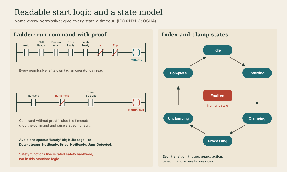
For the infeed conveyor, the run command might need all of these in series:
Auto_Mode · Drill_Station_Ready · Drive_Ready · Guards_Closed · No_Jam · No_Fault · Run_Request
Don’t collapse these into one bit called Ready. When the conveyor won’t start, the operator’s question is why, and named intermediate tags (Drive_NotReady, Jam_Detected) answer it on the HMI without a laptop.
A classic interlock: a reversing motor has a forward contactor and a reverse contactor, and both on at once is a dead short. Each rung includes a normally closed contact from the other output, so forward can’t energize while reverse is on, and vice versa 1. Reversing starters commonly add a mechanical interlock between the contactors, because the program shouldn’t be the only thing standing between you and a short.
Quick check
Clamp closed is a permissive for the drill; forward and reverse never both on is an interlock.
A sequence with timeouts
The drill station does the same steps every cycle. Write them as states, one active at a time, each with an action, a condition to move on, and a timeout:
| Step | Action | Move on when | Timeout | On timeout |
|---|---|---|---|---|
| 1 Idle | nothing | part present and auto mode | none | — |
| 2 Clamp | turn on clamp solenoid | clamp-closed switch on | 2 s | fault: “clamp did not close” |
| 3 Drill down | drill motor on, feed down | depth switch on | 8 s | fault: “drill did not reach depth” |
| 4 Drill up | feed up | drill-home switch on | 4 s | fault: “drill did not return” |
| 5 Unclamp | clamp solenoid off | clamp-open switch on | 2 s | fault: “clamp did not open” |
| 6 Done | tell robot “part ready” | robot confirms pickup | 30 s | alarm: “robot did not pick part” |
Every waiting step ends one of two ways: it completes, or it times out to a fault state that names the step. Without timeouts, a stuck sensor leaves the machine sitting silently in step 2 and someone spends twenty minutes guessing. IEC 61131-3’s sequential function chart language is built for exactly this step-and-transition structure 2.
What a fault state does depends on the hazard: hold the clamp closed so the part doesn’t drop, retract the drill, stop the conveyor. Decide it per step, and decide what the operator must do to recover.
Quick check
Every waiting step needs a timeout and a defined fault path.
Alarms that help
A good alarm text says what happened and where to look: “Clamp did not close in 2 s: check air pressure and clamp-closed switch LS-201.” Show the first-out alarm (the root cause) above the pile of follow-on alarms it triggered. Reset should clear the alarm once the condition is fixed, and should never restart motion by itself.
Safety stays separate
The PLC program can ask for a stop, but an ordinary PLC isn’t the safety system. Emergency stops, guard interlocks, and light curtains run through safety-rated relays or safety PLCs designed and validated for that job, as OSHA’s guidance on robot systems describes 3. The standard PLC watches the safety circuit’s status so it can show what tripped and sequence a clean restart.
Playback is optional. If the player is unavailable, open the video at its source.
Try it
Write the rungs for the infeed conveyor: a seal-in with an NC stop, the seven permissives above, and a fault that latches if RunCmd is on for 3 seconds without RunningFb. Then add a step 2½ to the drill sequence that checks air pressure before drilling, with its own timeout and alarm text.
Lesson complete
Nice work.
Sources for this lesson
- 1Tony R. Kuphaldt. Lessons in Electric Circuits, Volume IV (Digital), Chapter 6: Ladder Logic. ibiblio.org (Design Science License). verifiedLadder diagrams have two rails (L1 hot, L2 grounded) and rungs, with the load on the grounded side so a ground fault blows a fuse instead of energizing the load; seal-in (latch) contacts in parallel with a start button; interlocks; fail-safe design starts from the most likely failure, which for wiring is an open circuit; the PLC was introduced in the late 1960s as the Modicon by Bedford Associates to replace relay logic; inputs use opto-isolators, outputs use transistors, TRIACs, or relays; program contacts and coils are bits in memory and can be reused; a start-stop circuit with the stop button wired normally open cannot be stopped if its wire breaks, so wire the stop button normally closed and use a normally open contact in the program.
- 2IEC 61131-3:2025 - Programmable Controllers, Part 3: Programming Languages. International Electrotechnical Commission. 2025. verifiedCurrent syntax and semantics for structured text, ladder diagram, function block diagram, and sequential function chart organization. Cited at: SFC.
- 3OSHA Technical Manual, Section IV, Chapter 4 - Industrial Robot Systems and Industrial Robot System Safety. Occupational Safety and Health Administration. 2021. verifiedRobot-system components, lifecycle hazards, risk assessment, safeguards, collaborative modes, training, evaluation, and applicable U.S. requirements. Cited at: safety considerations.