PLC Scan, I/O & Control Architecture
What a PLC is and how it runs: input modules, a program that solves top to bottom, output modules, and a scan that repeats every few milliseconds. Why a short sensor pulse can be missed (worked with conveyor numbers), the I/O list as the contract between electrical and controls, command versus proof, and where the PLC sits between field devices and business systems.
- 6 min
- 7 steps
- 3 questions
- Lesson 61 of 78
In this lesson
- What a PLC is
- The scan
- Why short pulses get missed
- The I/O list
- Command is not proof
- Where the PLC sits
- Try it
Open alongside this lesson
-
IEC 61131-3:2025 - Programmable Controllers, Part 3: Programming Languages (opens in a new tab)
Use the overview to distinguish ladder, function blocks, structured text, and sequential function charts.
Picking up where you left off.
What a PLC is
A programmable logic controller is an industrial computer built to replace racks of relays. The first, the Modicon, came from Bedford Associates in the late 1960s; the idea was a solid-state box with a stored program that behaves like the relay logic electricians already knew 1. That’s why the most common PLC language still looks like a relay schematic.
A PLC has three parts that matter:
- Input modules. Each terminal reads a field device: a pushbutton, limit switch, photoeye, pressure switch. Inside, an opto-isolator turns the field voltage (often 24 V DC or 120 V AC) into a clean logic bit, with an LED on the front showing its state 1.
- The program. Contacts and coils on the screen aren’t real; they’re bits in memory. An input bit can be used in as many rungs as needed, which is one reason a PLC beats hardwired relays 1.
- Output modules. Transistors, TRIACs, or small relays switch real loads: contactor coils, solenoid valves, stack lights 1.
IEC 61131-3 defines the standard languages: ladder diagram, function block diagram, structured text, and sequential function charts for organizing steps 2.
Through this course, picture one small cell: an infeed conveyor brings steel brackets to a clamp-and-drill station, and a robot unloads finished brackets to an outfeed conveyor.
The scan
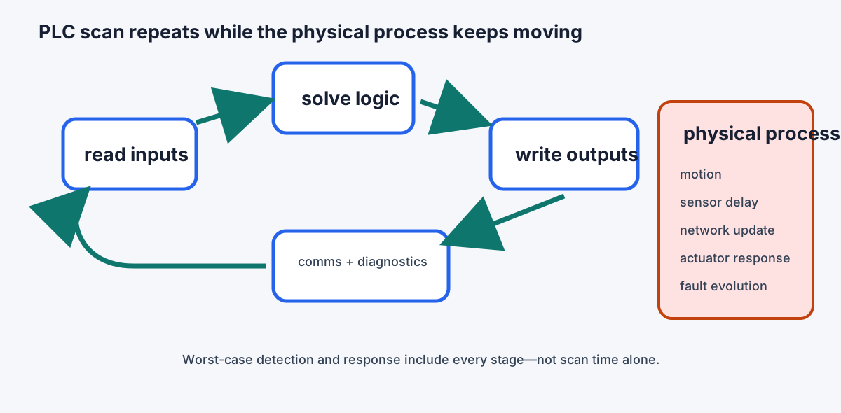
A PLC doesn’t watch its inputs continuously. It runs a loop, the scan:
- Read inputs: copy every input’s state into an input image table.
- Solve the program, rung by rung, top to bottom, using that snapshot.
- Write outputs: copy the results to the output modules.
- Housekeeping: communications, diagnostics. Then repeat.
A small program scans in a few milliseconds. Because the program works from a snapshot, an input that changes in the middle of step 2 isn’t seen until the next scan, and an output set late in the program doesn’t reach the field until step 3.
Quick check
The program works on a snapshot of the inputs taken at the start of the scan.
Why short pulses get missed
At the drill station, a photoeye watches for the leading edge of each bracket. Suppose the infeed belt runs at 1 m/s:
- A bracket 40 mm long blocks the beam for 40 ms. A PLC with a worst-case 12 ms scan plus input filter will see it every time.
- The gap between two touching-but-not-quite brackets might be 6 mm: 6 ms of light. That can fall entirely between two input reads, and the PLC never knows the parts were separate.
Fixes, roughly in order of cost: slow the belt or space the parts; use the input module’s high-speed counter or interrupt input; put the counting in a faster periodic task; or use a sensor with built-in pulse stretching. “The PLC is fast” is not a timing analysis; the numbers are.
Quick check
Fixes include a high-speed counter or interrupt input, a faster task, a longer target, or slower speed.
The I/O list
Before anyone writes code, the electrical designer and the programmer agree on an I/O list, one row per point. For the drill station:
| Tag | Device | Type | Normal state | On loss of signal |
|---|---|---|---|---|
| PE_PartPresent | photoeye at stop | 24 V DC in | off (no part) | reads “no part”: station waits |
| LS_ClampClosed | clamp limit switch | 24 V DC in | off | reads “open”: drill can’t start |
| PB_Stop | stop button, NC contact | 24 V DC in | on (circuit closed) | reads “stop”: cell stops |
| SOL_Clamp | clamp valve solenoid | 24 V DC out | off | clamp opens (spring return) |
| M_Drill | drill motor contactor | 24 V DC out | off | drill stops |
The last column is the point. A broken wire looks like an input turning off, so each input is wired so that “off” is the safe interpretation. That’s why stop buttons use normally closed contacts: if the stop button were wired normally open, a broken wire would mean the button could never stop the machine; wired normally closed, a broken wire stops it 1.
Command is not proof
Conveyor_RunCmd is what the PLC asked for. Conveyor_RunningFb is what happened: an auxiliary contact on the motor starter, a drive’s “running” status, or a speed sensor on the tail pulley. Keep them as separate tags and compare them. If the command has been on for 2 seconds and there’s no feedback, something is wrong (a tripped overload, a broken belt) and the program should drop the command and raise a specific alarm.
Quick check
Command is not proof; a tripped overload or broken coupling leaves the command on and the belt stopped.
Where the PLC sits
ISA-95 describes the layers of a plant 3:
- Field devices sense and act.
- PLCs and motion controllers run deterministic control.
- HMI and SCADA let people supervise and record.
- MES schedules and tracks production.
- ERP handles orders, inventory, and money.
Design so a slow or failed upper layer never stops the lower one: if the MES server goes down, the drill station should finish its part and wait, not crash. NIST’s guide to operational technology security makes the same point from the security side: OT controls physical equipment, so availability and safety come first, and PLCs need managed accounts, backups, change control, and network segmentation rather than being treated like office PCs 4.
Playback is optional. If the player is unavailable, open the video at its source.
Try it
Write the I/O list for the infeed conveyor: a run command, running feedback, a photoeye at the stop, a jam photoeye, and a downstream-ready signal from the drill station. For each, write what a broken wire reads as and whether that’s safe. Then work out the shortest part gap your belt speed allows for a 10 ms scan.
Lesson complete
Nice work.
Sources for this lesson
- 1Tony R. Kuphaldt. Lessons in Electric Circuits, Volume IV (Digital), Chapter 6: Ladder Logic. ibiblio.org (Design Science License). verifiedLadder diagrams have two rails (L1 hot, L2 grounded) and rungs, with the load on the grounded side so a ground fault blows a fuse instead of energizing the load; seal-in (latch) contacts in parallel with a start button; interlocks; fail-safe design starts from the most likely failure, which for wiring is an open circuit; the PLC was introduced in the late 1960s as the Modicon by Bedford Associates to replace relay logic; inputs use opto-isolators, outputs use transistors, TRIACs, or relays; program contacts and coils are bits in memory and can be reused; a start-stop circuit with the stop button wired normally open cannot be stopped if its wire breaks, so wire the stop button normally closed and use a normally open contact in the program.
- 2IEC 61131-3:2025 - Programmable Controllers, Part 3: Programming Languages. International Electrotechnical Commission. 2025. verifiedCurrent syntax and semantics for structured text, ladder diagram, function block diagram, and sequential function chart organization. Cited at: language suite.
- 3ISA-95 - Enterprise-Control System Integration. International Society of Automation. verifiedTechnology-neutral models for equipment hierarchy, manufacturing operations, and the interfaces among plant control and business systems. Cited at: levels and interfaces.
- 4NIST SP 800-82 Rev. 3 - Guide to Operational Technology Security. National Institute of Standards and Technology. 2023. verifiedSecurity guidance for OT systems, including PLC, DCS, SCADA, physical-process interactions, reliability, performance, and safety constraints. Cited at: OT scope.