Electrical Architecture, Power & Interfaces
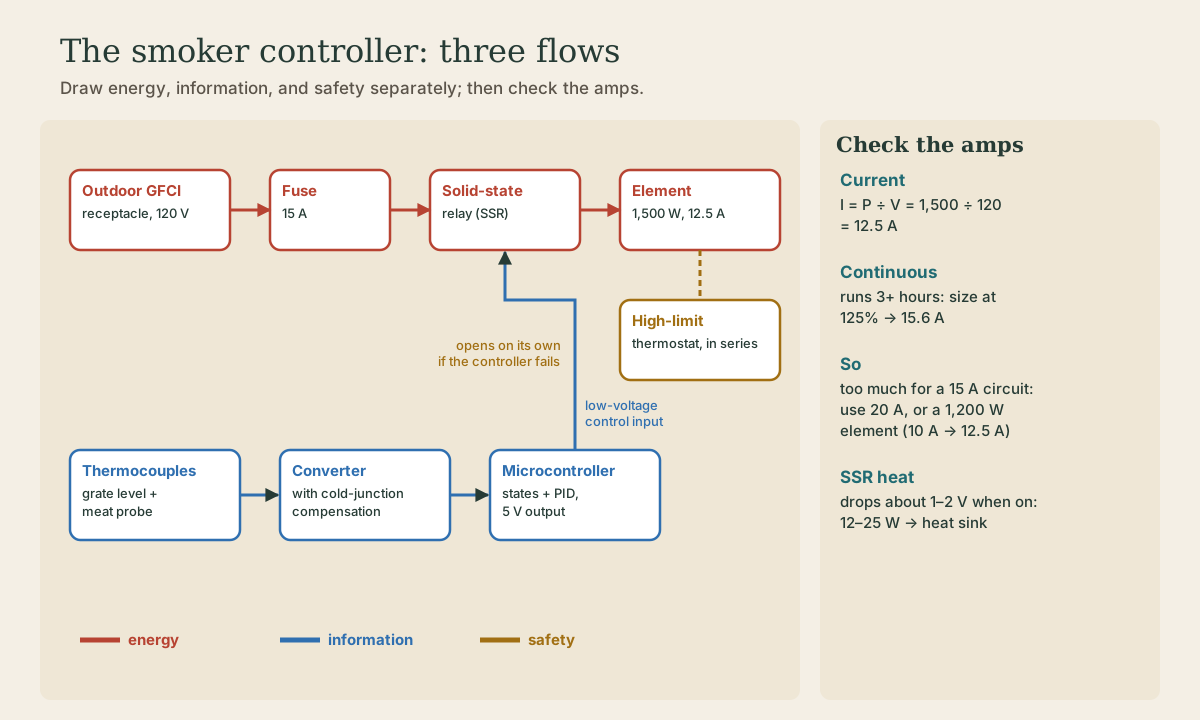
The course builds one mechatronic system end to end: a temperature controller for an electric smoker that holds 225 °F and knows when the meat is done. This lesson draws its three flows (energy, information, and safety), sizes the power (1,500 W at 120 V is 12.5 A, which a load running three hours or more turns into 15.6 A of circuit capacity), keeps line voltage inside a solid-state relay with a low-voltage control input, adds an independent high-limit thermostat and a GFCI outdoor outlet, and writes the interface contract for every connection.
- 5 min
- 5 steps
- 3 questions
- Lesson 49 of 78
In this lesson
- The system
- Three flows
- Size the power
- Interface contracts
- What to take from this
Picking up where you left off.
The system
This course follows one machine from wiring diagram to tuned controller: an electric smoker controller. The smoker is a metal box with a heating element in the bottom, a pan of wood chips on the element for smoke, racks of meat, and a door. The controller has to hold the chamber at a setpoint, say 225 °F, for hours, watch a probe in the meat, and finish when the meat reaches its target. The bacon lesson in the food preservation and butchering courses, for example, smokes at 225–250 °F until the meat reaches 160 °F inside 1.
It’s a good mechatronics project because it has everything: line-voltage power switched by low-voltage electronics, a sensor that produces microvolts in an electrically noisy box, an actuator with a long, slow response, a state machine, and a feedback loop to tune. It’s also a real thing worth having.
Three flows
Before any schematic, draw the system three times, one flow at a time:
- Energy (red): plug → outdoor GFCI receptacle → fuse → solid-state relay (SSR) → element → back. This is the only path at 120 V.
- Information (blue): grate thermocouple and meat probe → a thermocouple converter with cold-junction compensation → microcontroller → the SSR’s low-voltage input. Everything here is a few volts.
- Safety (orange): an independent high-limit thermostat wired in series with the element. It opens at a fixed temperature on its own, whatever the controller is doing. Solid-state relays usually fail shorted, which means stuck on; software can hang; a thermocouple can fall out of the chamber and read room temperature, so the controller turns the heat up. The high limit catches all three.
The outlet matters too. Outdoors, near damp ground and a metal box, a GFCI compares the current going out with the current coming back and trips at a 5 mA difference, within as little as 1/40 second 2. Plug the smoker into one.
Quick check
A solid-state relay usually fails shorted, which means stuck on.
Size the power
Electrical power is voltage times current, so current is P ÷ V 3. A 1,500 W element on 120 V draws 1,500 ÷ 120 = 12.5 A. A smoke runs ten hours, and the electrical code treats a load that runs three hours or more as continuous and sizes the circuit for 125 percent of it: 12.5 × 1.25 = 15.6 A. That’s more than a 15 A circuit can carry. Two fixes:
- run it on a 20 A circuit, or
- use a 1,200 W element: 10 A, or 12.5 A at 125 percent, fine on 15 A. It heats a bit slower, which the controller can handle.
The SSR needs attention too. When it’s on, it isn’t a perfect switch: it drops roughly 1 to 2 volts, so at 12.5 A it turns 12 to 25 W into heat inside its case. Mount it on a heat sink, outside the hot smoker, in a box with ventilation.
Quick check
Use a 20 A circuit or a smaller element (1,200 W draws 10 A).
Interface contracts
Mechatronic systems usually fail at the connections between parts, not inside them. For each connection, write down a short contract:
| Field | Thermocouple → converter | Controller → SSR |
|---|---|---|
| Connector, pins | type K mini-plug | 2-pin terminal block |
| Signal | about 41 µV/°C, about 4 mV at 225 °F | 3–32 V DC to turn on |
| Reference | floating (ungrounded probe) | controller ground |
| Update | converter reads 4 times a second | 2-second time-proportioning window |
| Fault behavior | open probe flagged, heater off | input lost → SSR off |
| Owner | you | you |
The fault row is the one people skip. Decide now what each failure does, and make sure “off” is what happens when something breaks.
Quick check
Most mechatronic failures happen at interfaces.
What to take from this
Draw energy, information, and safety as separate flows; keep line voltage on one short path through an SSR, with everything else low voltage. Size the power: 1,500 W is 12.5 A, and a three-hour-plus load is sized at 125 percent, so use a 20 A circuit or a 1,200 W element. Heat-sink the SSR. Add an independent high-limit thermostat and a GFCI outlet, and write an interface contract for every connection, especially what each failure does.
Lesson complete
Nice work.
Sources for this lesson
- 1Joy Waite-Cusic, Jared Hibbard-Swanson. Making Cured Bacon at Home (PNW 784). Oregon State University Extension. 2025. verifiedDry cure or wet brine; Prague Powder #1 is 6.25 percent sodium nitrite and 93.75 percent salt, dyed pink and not the same as Himalayan pink salt; 1 teaspoon per 5 pounds of meat; dry-cured bacon is capped at 200 ppm nitrite commercially; Cure #2 not recommended for bacon (nitrosamines at high heat); cure 5-7 days at 40 F, flipping daily; smoke at 225-250 F to 160 F internal; refrigerate up to 7 days, freeze within 4 months.
- 2Controlling Electrical Hazards (OSHA 3075). Occupational Safety and Health Administration. 2002. verifiedConductors and insulators; impurities make water conduct, and wet skin conducts; shocks happen when the body completes a path between both wires, a wire and ground, or an energized metal part and ground; effects of current hand to foot for one second: under 1 mA not felt, 1 mA faint tingle, 5 mA slight shock, 6-30 mA painful and the let-go range, 50-150 mA respiratory arrest and possible death, 1,000-4,300 mA the heart stops pumping, 10,000 mA cardiac arrest and burns; fuses and breakers protect conductors and equipment; GFCIs compare outgoing and returning current and trip at a 5 mA difference within as little as 1/40 s; AFCIs detect arcing.
- 3University Physics, Volumes 1–3. OpenStax (Rice University). verifiedOpen calculus-based physics. Vol 1 mechanics; Vol 2 thermodynamics and electricity & magnetism; Vol 3 optics & modern physics.