Correcting a Switch Loop
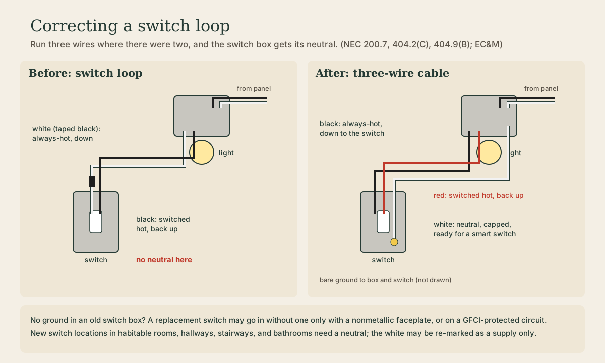
The permanent fix for an old switch loop is to replace its two-wire cable with three-wire cable: black down as the always-hot supply, red back up as the switched hot, and the white as a real neutral, capped in the switch box until a smart switch needs it. How to diagnose what you've got first, the common mis-wirings you'll find in an old house, what to do when the switch box has no ground, and when it's simpler to leave the loop alone.
- 5 min
- 7 steps
- 3 questions
- Lesson 78 of 111
In this lesson
- Diagnose first
- The fix: three-wire cable
- What you run into
- No ground in the box
- When to leave it alone
- Try it
Picking up where you left off.
The first part of this course explained what a switch loop is: power goes to the light first, and a two-wire cable runs down to the switch, so there’s no neutral in the switch box. This lesson is about fixing one for good.
Diagnose first
Before you buy anything, find out what’s really in the boxes. Turn off the breaker or pull the fuse, confirm the switch box and light box are dead with a tester, and open both.
- One two-wire cable at the switch, both wires on the switch, and a bundle of whites in the ceiling box: a switch loop.
- Which wire is which? The code allows the white in a switch-loop cable only as the supply to the switch, permanently re-marked, never as the return to the light 1. In an old house you’ll often find it backwards, and often not marked. With the power off, trace each conductor at the light box: the one spliced to the incoming hot is the supply.
- Whites spliced together in the switch box, with a cable continuing on: power comes to the switch first. You already have a neutral.
Photograph every box before you disconnect anything. Old work can be more creative than any diagram.
Quick check
Old work is often the other way around, and often not re-marked at all.
The fix: three-wire cable
The permanent fix is to replace the two-wire cable between the light and the switch with a three-wire cable (black, red, white, and bare ground), so the switch box gets a neutral. That is what the code requires at new switch locations in habitable rooms, hallways, stairways, and bathrooms 1, and replacing the cable is new work held to today’s code 2.
Wiring it, with the power off:
- At the light box, connect the incoming hot to the new cable’s black. That’s the always-hot supply going down to the switch.
- At the switch, connect the black to one terminal and the red to the other. The red carries the switched hot back up.
- At the light box, connect the red to the fixture’s hot lead.
- At the light box, splice the new cable’s white into the neutral bundle with the fixture’s neutral. At the switch, cap it with a wire nut and fold it into the back of the box. It’s there for a smart switch, timer, or occupancy sensor later.
- Connect the bare grounds at both boxes to the ground in the light box and to the switch’s green screw.
The black-down, red-back pattern is a common convention; what matters is that only hot conductors are switched 1 and that the white is never used as anything but a neutral in the new cable.
Quick check
Black goes down as the always-hot supply and red comes back as the switched hot.
What you run into
Fishing the cable. The old cable often can’t pull the new one through, because it’s stapled or knotted around framing. In a balloon-framed house, fishing from the attic down the stud bay is often easiest; see the fishing lesson in the first module.
No ground at the light. If the circuit itself has no equipment ground, a new three-wire cable can’t create one. The neutral fix still works; the grounding question is next.
Three-way switches. Two switches on one light multiply the possible old wiring patterns. The same principle applies, but label every conductor at every box before you start, and use the Residential Electrical course’s three-way diagrams to plan it.
No ground in the box
Old switch boxes often have no ground at all. For a replacement switch, the code accepts that if the existing wiring has no equipment grounding conductor and either the faceplate is nonmetallic or the switch is GFCI-protected 3. Plastic plates are cheap insurance. Never connect a switch’s ground screw to the white wire.
Quick check
Never use the neutral as a ground.
When to leave it alone
If the walls are closed and the light works, you don’t have to touch the loop. Old work that isn’t a hazard may stay 2. Tape the white black at both ends so it’s identified, and if you want a smart switch, choose one rated to work without a neutral, which the code allows as a replacement where a neutral can’t be added without removing finish materials, up to five per circuit 1. Correct the loop the next time the wall or ceiling is open anyway.
Try it
Pick the switch you most want to make “smart.” Shut off its circuit, verify it’s dead, and open the switch and light boxes. Sketch every wire and how it’s connected. Decide: three-wire cable now, or a no-neutral smart switch until the next remodel?
Lesson complete
Nice work.
Sources for this lesson
- 1NEC Requirements for Switches. EC&M (Electrical Construction & Maintenance). verifiedOnly phase (hot) conductors may be switched in 3-way and 4-way circuits [404.2(A),(B)]. A permanently reidentified white conductor in a cable may be used as a switch leg [200.7(C)(1)]. Switches controlling line-to-neutral lighting loads need a neutral at switch locations serving bathrooms, hallways, stairways, and habitable rooms [404.2(C)], with exceptions. Replacement switches needing line-to-neutral voltage to power electronics require a neutral [404.22], except in locations wired before 404.2(C) where the neutral can't be extended without removing finish materials; no more than five such no-neutral electronic switches per branch circuit and 25 per feeder.
- 2Wis. Admin. Code SPS 316.003, 316.021, 316.210, and 316.406. Wisconsin Legislature. 2026. verifiedRegister September 2026. SPS 316.003(1): the chapter applies to all new installations, reconstructions, alterations, and extensions. (3) Existing installations shall conform to the electrical code that applied when they were installed; where a hazard exists or is created, the authority having jurisdiction may require compliance with current code. (4) Repairs conform to the code that applied when installed, with the same hazard provision. (6) Additions and alterations comply with the chapter at the time of permit application or, with no permit, the beginning of the project. SPS 316.021: installations known to be defective so as to endanger life or property shall be promptly repaired, disconnected, or isolated. SPS 316.210(2): NEC 210.12(E) (AFCI for branch-circuit extensions, modifications, or replacements) is not included. SPS 316.406(1): NEC 406.4(D)(4) (AFCI for replacement receptacles) is not included.
- 3Mike Holt. Stumped by the Code? October 2010. EC&M (Electrical Construction & Maintenance). 2010. verifiedOctober 20, 2010 (2008 NEC). The metal mounting yoke of a replacement switch isn't required to be connected to an equipment grounding conductor if the wiring to the existing switch doesn't contain one, and the switch faceplate is nonmetallic or the replacement switch is GFCI-protected [404.9(B) Ex].