Reading Frame Drawings and Timber Lists
How a frame is described on paper - plan, elevations, bent drawings, joint details, and the timber list - and how to read the reference faces and marks that tie each timber to its place.
- 4 min
- 6 steps
- 3 questions
- Lesson 97 of 111
In this lesson
- Drawings describe a frame in layers
- Dimensions and conventions
- The timber list
- Reference faces and marks
- Reading joints on a drawing
- What to take from this
Picking up where you left off.
Drawings describe a frame in layers
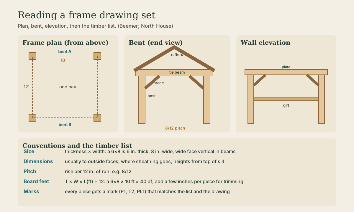
A timber frame design is usually a small set of drawings, each answering a different question 1:
- Floor plan / frame plan: the building’s footprint from above, showing post locations, bents, bays, sills, and dimensions to post centers or outside faces.
- Bent drawings (cross-sections): each bent as seen from the end, showing posts, tie beam, braces, and often roof framing, with heights and timber sizes.
- Wall elevations (side views): the long walls, showing plates, girts, braces, and door and window openings.
- Roof framing plan: rafter spacing, ridge, purlins.
- Joint details: enlarged views of each joint type with dimensions: tenon length and thickness, peg locations, housing depths, brace angles.
The North House “Build Your Own” frames are documented this way. Their overview sheet shows a 10×12 frame and a 10×16 frame in plan and elevation and a 13½×13½ sauna frame with a porch and changing room, drawn by timber framer Peter Henrikson 2.
Dimensions and conventions
- Dimensions in timber framing are often to the outside face of the frame (the face that sheathing nails to) rather than to centers, because square-rule and mill-rule layout work from those faces. Check which the drawing uses.
- Heights are given from the top of the sill or top of the foundation.
- Roof pitch is given as rise per 12 inches of run, for example 8/12, or as an angle.
- Timber sizes are written thickness × width, e.g. 6×8 means 6 inches thick by 8 inches wide, with the wider dimension usually vertical in beams so they’re stiffer.
The timber list
The timber list (cut list) turns the drawings into materials 1. For each piece:
| Mark | Name | Qty | Section | Length | Species |
|---|---|---|---|---|---|
| P1–P4 | Posts | 4 | 6×6 | 8’-6” | E. white pine |
| T1–T2 | Tie beams | 2 | 6×8 | 10’-6” | E. white pine |
| PL1–PL2 | Plates | 2 | 6×6 | 12’-6” | E. white pine |
An illustrative layout, not a real plan.
Lists usually add a few inches to every length for trimming checked ends and squaring. Sum the board feet (thickness × width × length in feet ÷ 12) to price the order: a 6×8 × 10 ft is 40 board feet.
Quick check
The timber list is the shopping and milling list: each piece, its section and length (with a few inches extra), and how many.
Quick check
6 × 8 × 10 ÷ 12 = 40.
Reference faces and marks
Before layout begins, each timber gets:
- A name and mark, written on it, matching the drawings: P1, T2, or a bent and position code.
- Reference faces: usually two adjacent faces, chosen as the outside and top faces of the frame, from which all joinery on that timber is measured. In square rule and mill rule they’re the faces that line up with the building’s outside planes.
- Arrows or symbols showing which end is which and which face points out.
Historic frames used marriage marks: chiseled Roman numerals on each tenon and its mortise so pieces fitted together in a scribe-rule layout could be reassembled correctly at the raising 3.
Reading joints on a drawing
A joint detail typically shows:
- the shoulder location (where the beam meets the post face);
- tenon thickness (often 1 1/2 inches in small frames, matching a 1 1/2-inch framing chisel), length, and width;
- peg hole locations from the shoulder and edge;
- housing depth, if any;
- for braces, the run and rise (for example 24 by 24 inches for a 45° brace) and where the brace meets the post and beam faces.
Before you cut anything, check that every mortise on a post has a matching tenon on the timber that meets it, at the same height and from the same reference face. Most layout mistakes are discovered here, on paper, where they cost nothing.
What to take from this
Frame drawings come in layers: plan, bent sections, wall elevations, roof plan, and joint details. The timber list names, counts, sizes, and lengths every piece with trim allowance. Each timber gets a mark and reference faces from which all its joints are measured. Check every joint against its mate on paper before cutting.
Practice
Layout is measured from chosen reference faces, and marks like A1 or Roman numerals record where each timber and joint belongs.
Lesson complete
Nice work.
Sources for this lesson
- 1Will Beemer. Learn to Timber Frame: Craftsmanship, Simplicity, Timeless Beauty. Storey Publishing. 2016. verifiedHeartwood School's step-by-step guide from timber sourcing to a finished 12×16 frame, including layout, joinery, and raising. Cited at: Design and Drawings; Timber List.
- 2Peter Henrikson. Build Your Own Timber Frame: 10×12, 10×16, and 13.5×13.5 Sauna Frames. North House Folk School. 2008. verifiedOverview drawings of North House's stock small frames, drawn by timber framer Peter Henrikson.
- 3Jack A. Sobon, Roger Schroeder. Timber Frame Construction: All About Post-and-Beam Building. Storey Publishing. 2012. verifiedClassic reference (first published 1984) on timber selection, tools, joinery, frame types, assembly, and raising. Cited at: Layout.