Making Good Connections
Most electrical failures happen at connections. How to make a wire-nut splice that holds (strip about 3/4 inch, twist tight, tug every wire, pick the right size), wrap a wire clockwise under a screw terminal, keep one wire per screw, use pigtails and grounding pigtails, keep the wire colors straight, and why loose or corroded joints, especially copper to aluminum, heat up and drop voltage.
- 4 min
- 7 steps
- 3 questions
- Lesson 53 of 111
In this lesson
- Why connections matter
- Wire-nut splices
- Screw terminals
- Pigtails
- Colors
- Check your work
- What to take from this
Picking up where you left off.
Why connections matter
A wire run is a continuous conductor with known resistance. A connection is a place where two pieces of metal merely touch. If that contact is loose, corroded, or too small, it has resistance, and resistance with current flowing makes heat and voltage drop. A voltage at the load lower than the wire size predicts usually means a bad connection somewhere 1. Improperly joined copper and aluminum, and wet aluminum connections, corrode into high-resistance joints 1.
Connections are made in boxes so that if one does fail, it fails inside a noncombustible or rated enclosure 2.
Wire-nut splices
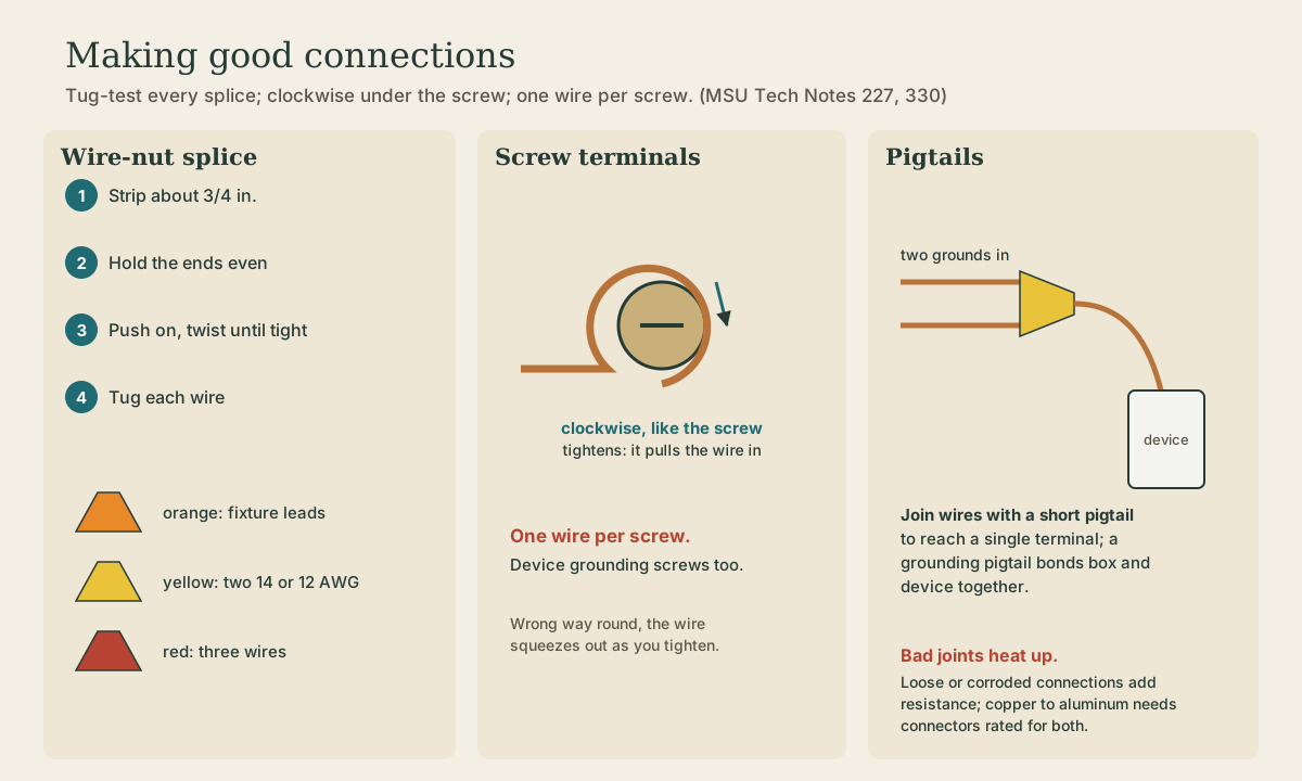
The usual splice is a twist-on connector, or wire nut. MSU’s procedure 2:

- Strip about 3/4 inch of insulation from each wire.
- Hold the wires together with the ends even.
- Push the connector on and twist until it’s tight.
- Tug each wire. If one comes out, take it apart and redo it.
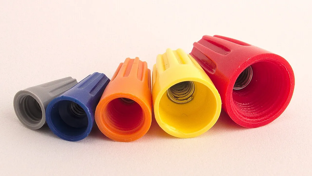
Sizes are color-coded. The common yellow joins two 14 or 12 AWG wires; red, the next size up, is for three; smaller orange is for fixture leads 2. Check the range printed on the package for your exact combination. MSU calls an improperly installed wire nut “a frequent cause of failure of electrical circuits” 2.
Quick check
MSU calls an improperly installed wire nut a frequent cause of circuit failure.
Screw terminals
On switches and receptacles, wrap the stripped end around the screw clockwise, the direction the screw turns to tighten. Tightening then pulls the loop in snug; wrapped the other way, the wire squeezes out from under the head, and stranded wire frays out 2.
Put only one wire under each screw. Device terminals, including the green grounding screw, are rated for one wire 2.
Quick check
Tightening then draws the wire in instead of squeezing it out.
Pigtails
When two or more wires need to reach one terminal, or a circuit continues through a box to the next outlet, join them in a connector with a short pigtail, a 6-inch piece of the same wire, and land just the pigtail on the device. The circuit then doesn’t depend on the device to keep going downstream.
Grounds work the same way. The equipment grounding wires from each cable are spliced together with pigtails to the receptacle’s green screw and, in a metal box, to the box itself through a grounding screw or clip 2. The grounding path has to stay continuous through every box 3.
Quick check
Terminals are rated for one wire.
Colors
Keep the colors meaning what they should 3:
- Black or red: hot (ungrounded).
- White: neutral (grounded), always.
- Bare or green: equipment ground, never carrying normal current.
On a receptacle, the hot goes to the brass screw and the neutral to the silver one, which keeps the wide slot on the neutral.
Check your work
Before closing a box: every splice tug-tested, no bare copper showing past a connector, loops clockwise and tight, one wire per screw, grounds continuous, and the wires folded back neatly without forcing the device in. Then turn the power on and test the outlet with a plug-in tester.
Playback is optional. If the player is unavailable, open the video at its source.
What to take from this
Connections fail far more often than wire. For a wire-nut splice, strip about 3/4 inch, hold the ends even, twist tight, tug every wire, and use the right size. Wrap wires clockwise under screws, one wire per screw, and use pigtails to join several wires to a device or ground. White is always neutral, bare or green always ground, hot to brass and neutral to silver. Loose or corroded joints, especially copper to aluminum, heat up and drop voltage.
Lesson complete
Nice work.
Sources for this lesson
- 1Electrical Tech Note 227: Sizing Conductors to Minimize Voltage Drop. Michigan State University, Biosystems & Agricultural Engineering. verifiedSingle-phase voltage drop is 2 x I x R, with R for the one-way length; excessive drop wastes energy and burns out motors; high-resistance connections, including improper copper-aluminum joints and wet aluminum connections, also cause drop; the NEC recommends no more than 5 percent from source to farthest load, about 2 percent on feeders and 3 percent on branch circuits; Table 227.1 gives resistance per 1,000 ft (copper at 75 C: 14 AWG 3.14, 12 AWG 1.98, 10 AWG 1.24, 8 AWG 0.778 ohms).
- 2Electrical Tech Note 330: Wiring Circuits, Basic Rules. Michigan State University, Biosystems & Agricultural Engineering. verifiedEach hot wire is about 120 V to earth and 240 V hot to hot; voltages above about 15 V can be dangerous; NM-B cable for dwellings is commonly 14 AWG for 15 A circuits (white jacket), 12 AWG for 20 A (yellow), and 10 AWG for 30 A (orange); NM cable is for dry locations only; keep the equipment grounding conductor continuous; one wire per device screw terminal.
- 3Electrical Tech Note 228: Grounding, Bonding, and Equipotential Grids. Michigan State University, Biosystems & Agricultural Engineering. verifiedSystem grounding ties the neutral to earth at the service to limit voltage from lightning, surges, or contact with higher-voltage lines and to stabilize voltage to earth; the equipment grounding conductor (bare or green) carries fault current back so the breaker trips and limits touch voltage; the neutral is the grounded conductor and carries current; the equipment grounding wire and neutral terminate together in the service panel; bonding joins metal parts into one continuous path; current returns to its source, not into the earth for its own sake; electrodes should be under 25 ohms if possible; 0.14 A into a 25-ohm rod gives about 3.5 V neutral-to-earth voltage; GFCI receptacles trip at 5 mA; equipotential grids in livestock and pool areas.