Reading Construction Drawings
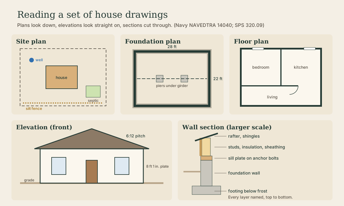
A set of house drawings is a few kinds of views of the same building. Plans look down (site, foundation, floor, framing), elevations look straight at each side, and sections cut through, with the wall section naming every layer from footing to roof. How to read scale (1/4 inch = 1 foot), dimensions, symbols, schedules, and specifications, worked through on a small house from the Navy's public-domain blueprint manual, plus what Wisconsin requires on the plans you submit.
- 5 min
- 7 steps
- 3 questions
- Lesson 2 of 111
In this lesson
- Views of one building
- Plans
- Elevations
- Sections and details
- Scale and dimensions
- Schedules and specifications
- What to take from this
Picking up where you left off.
Views of one building
A set of construction drawings shows the same house several ways, each an orthographic view: looking straight at one face, with no perspective 1. Learn which view answers which question and the set stops being overwhelming.
- Plans look straight down, as if the building were sliced horizontally.
- Elevations look straight at each side.
- Sections cut vertically through the building to show what’s inside a wall, floor, or roof.
- Details blow up a small area at a larger scale.
Plans
The Navy’s blueprint manual lists the common plans 1:
- Site plan (plot plan): the lot with its boundaries, contours, roads, utilities, trees, and existing structures, and the new building’s outline located from a reference line, so it can be staked out. Contour lines show existing and finished grades for the excavator. Wisconsin’s site plan must also show wells, surface water, the septic dispersal area, erosion-control measures, and the direction runoff flows 2.
- Foundation plan: a horizontal cut at the top of the foundation. In the manual’s example: an 8-inch concrete block wall, 22 by 28 feet, centered on a 10-inch-wide concrete footing, with two 12-inch square piers on 18-inch square footings carrying a center girder 1.
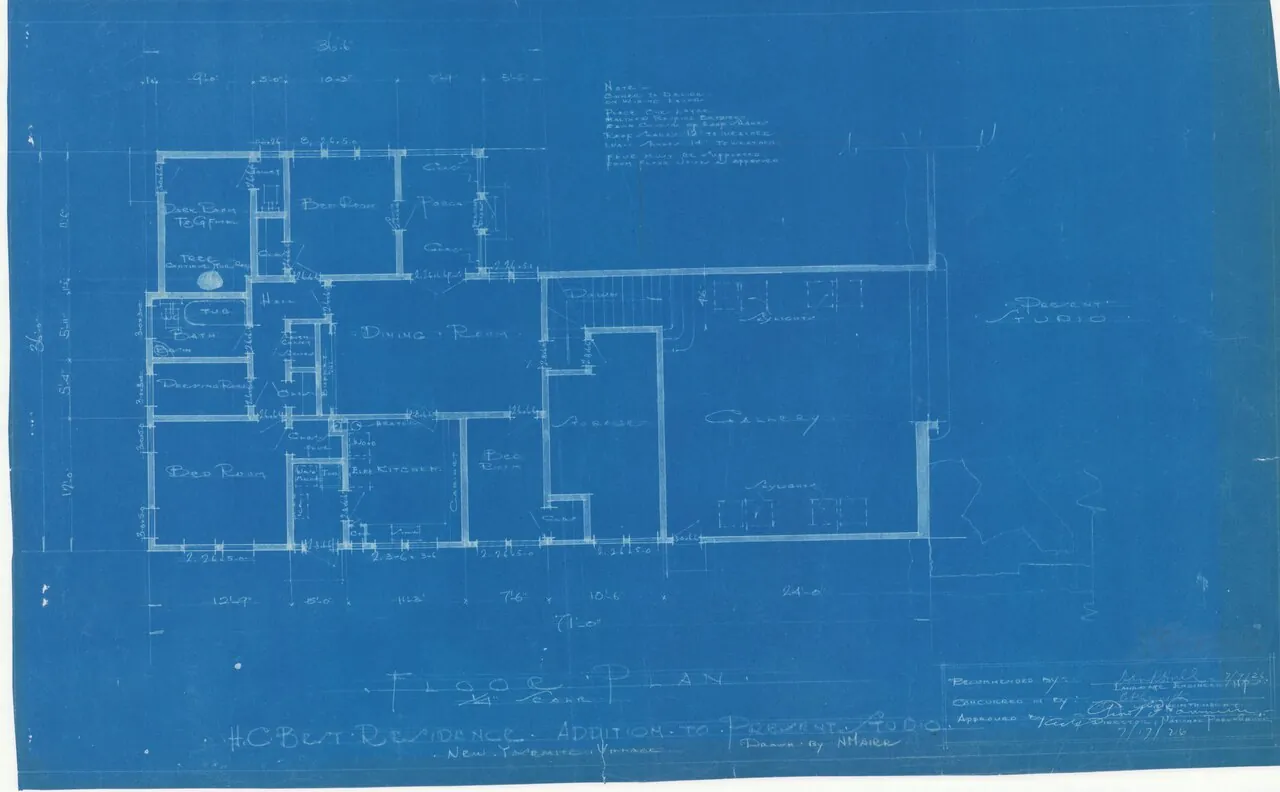
- Floor plan: a cut a few feet above each floor, showing walls and their thickness, door and window openings, partitions, rooms, and utilities 1. Wisconsin adds the use of each room, plumbing fixtures, heating layout, and wall-bracing details 2.
- Framing plans: the size, spacing, and layout of joists, studs, and rafters. The manual’s floor framing plan calls for 2×8 joists 16 inches on center (OC), lapped at the girder, with a row of cross bridging 1.
- Utility plans: heating, electrical, and plumbing layouts, which the foundation crew needs too, to leave openings in the right places 1.
Elevations
An elevation is a view of the front, rear, or a side, projected straight on. Elevations give the vertical dimensions: finished floor to the top plate, heights of door and window openings, roof pitch, chimney height, and where finished grade meets the foundation 1. Wisconsin requires them to show exterior materials, openings, roof, grade, footings, and foundation walls 2.
Roof pitch is written as rise over run, like 6:12: the roof rises 6 inches for every 12 inches it runs horizontally.
Sections and details
A section is a vertical cut. The most important are wall sections, drawn at a larger scale and read from the bottom up 1. In the manual’s masonry example: a concrete footing 1 foot 8 inches wide and 10 inches high; 12-inch block foundation wall; 2×8 floor joists 16 inches OC on 2×4 sills bolted to the wall; 2×6 ceiling joists and rafters; composition shingles on wood sheathing; and 8 feet 2 1/4 inches from finished floor to the top of the rafter plate. A small arrow-and-letter mark on the floor plan shows where each section is cut.
Details are larger still, for things too small to read on the plans: door and window framing, eaves, stair stringers, flashing 1.
Quick check
Sections are vertical cuts drawn at a larger scale, naming every layer.
Scale and dimensions
The scale in the title block tells you how drawing size relates to real size 1. House plans and elevations are usually 1/4 inch = 1 foot: 1 inch on paper is 4 feet. Sections and details are larger, such as 3/4 inch or 1 1/2 inches = 1 foot. Site plans are smaller, like 1 inch = 20 feet.
Dimensions are written in feet and inches (9′-2 1/4″). Prints shrink and stretch when copied, so read the written dimension rather than scaling the paper whenever one is given.
Quick check
Each inch on paper is 4 feet. Better still, read the written dimension; don’t scale a print if a dimension is given.
Schedules and specifications
Repeated items are tagged on the plans and listed in schedules: a window schedule gives each window’s size and type, and a door schedule the same for doors 1.
Specifications carry what can’t be drawn: material quality, concrete strength, lumber grades, brands, installation standards, and workmanship 1. When the drawings and specs disagree, ask before building either one.
Playback is optional. If the player is unavailable, open the video at its source.
Quick check
Specifications carry the information that can’t be drawn.
What to take from this
Plans look down (site, foundation, floor, framing, utilities), elevations look straight at each side and give the heights, and sections cut through, with the wall section naming every layer from footing to roof. Read scale from the title block (1/4 inch = 1 foot means 1 inch is 4 feet), but trust written dimensions over a ruler. Window and door schedules and the specifications fill in what the lines can’t say.
Lesson complete
Nice work.
Sources for this lesson
- 2Wis. Admin. Code ch. SPS 320, Uniform Dwelling Code: Administration and Enforcement. Wisconsin Department of Safety and Professional Services. verifiedThe UDC (chs. SPS 320-325) covers one- and two-family dwellings begun on or after June 1, 1980 (energy rules, SPS 322, from Dec. 1, 1978), including additions and alterations to them and barns or garages converted to homes; it doesn't cover older houses (unless a municipality adopts it), detached garages and accessory buildings, farm buildings, primitive rural hunting cabins, or repairs. A Wisconsin uniform building permit is required before any on-site construction, including excavation; applicants who aren't the owner living in the house need dwelling contractor certification; 2 sets of plans (site plan with erosion control, floor plans with wall bracing, elevations) plus energy data; plans need not be stamped by an architect or engineer; the permit expires in 24 months if the exterior isn't completed. Inspections: erosion control, foundation excavation (after forms and reinforcement, before concrete), reinforcement, foundation (before backfill), rough (basement floor, framing, electrical, plumbing, HVAC), insulation and vapor retarder, and final; work may proceed if an inspection hasn't happened by the end of the second business day after notice; occupancy needs a final inspection with no critical violations, or local rules apply after 5 business days.