Receptacles
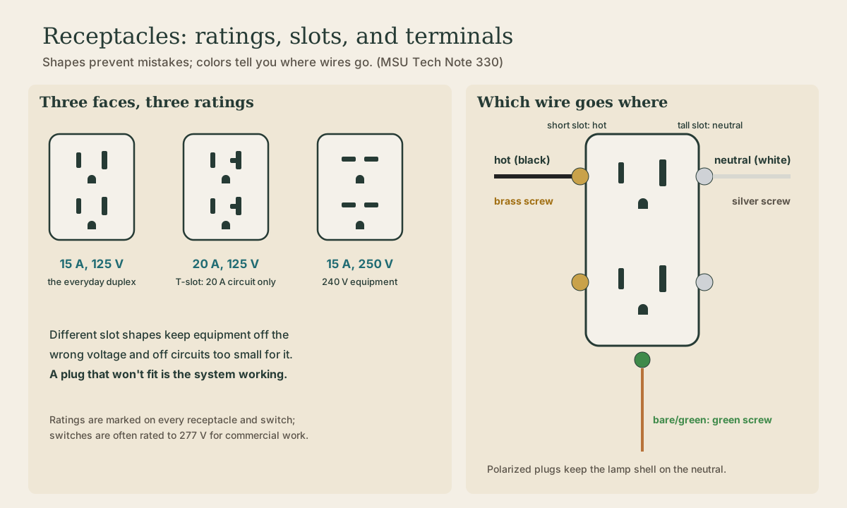
What a receptacle's shape and screws tell you. Slot shapes match plugs to voltage and current (the T-slot 20-amp receptacle belongs only on a 20-amp, 125-volt circuit; horizontal blades mean 240 volts); brass screws take the hot, silver the white neutral, green the ground; the tall slot is the neutral. Matching ratings, grounding self-grounding and ordinary devices, and where GFCI receptacles go.
- 4 min
- 6 steps
- 3 questions
- Lesson 54 of 111
In this lesson
- Shapes match plugs to circuits
- Which wire goes where
- Grounding the receptacle
- GFCI receptacles
- Replacing one
- What to take from this
Picking up where you left off.
Shapes match plugs to circuits
Receptacles, plugs, and switches carry voltage and current ratings, and their shapes are designed so equipment can’t be plugged into the wrong voltage or a circuit too small for it. The wrong match can damage equipment, overheat and start a fire, or even cause an electrical explosion 1.
The common types 1:
- 15 A, 125 V duplex: two vertical slots of different heights and a round ground hole. The everyday receptacle.
- 20 A, 125 V: the neutral slot is T-shaped, so it accepts both 15-amp and 20-amp plugs. Code permits it only on a 125-volt, 20-amp circuit.
- 15 A, 250 V: horizontal blades, for 240-volt equipment like a window air conditioner or shop tool.
Every receptacle and switch is marked with its ratings. Switches are often rated up to 277 volts, a voltage common in commercial buildings 1. A plug that won’t fit a receptacle is the system working: don’t modify either one.
Quick check
The T-slot accepts 20-amp plugs, so the circuit behind it must be able to carry 20 amps.
Which wire goes where
Devices are polarized: one side is meant for the neutral 1:
- Brass screws take the hot (black or red).
- Silver screws take the white neutral.
- The green screw takes the equipment ground.
On the face, the short slot is hot and the tall slot is neutral. Polarized plugs have one wider blade that only fits the neutral slot, so a lamp’s threaded socket shell, the part a finger might touch while changing a bulb, stays on the neutral.
A duplex has two screws on each side, joined by a breakaway tab. Use one screw per wire; feed through with pigtails or the second screw, never two wires under one 1.
Quick check
Hot to brass, neutral to silver, ground to green.
Quick check
Polarized plugs have a wider neutral blade that only fits the tall neutral slot.
Grounding the receptacle
Receptacles must be grounded. Some are self-grounding, picking up the ground through a mounting screw and spring clip against a grounded metal box. If you’re not sure a receptacle is self-grounding, run a short pigtail from the box’s grounding to its green screw 1. In a plastic box, the circuit’s ground wire lands directly on the green screw. The grounding path must stay continuous through every box 2.
GFCI receptacles
A GFCI receptacle protects people at its own outlet and, wired through its LOAD terminals, at the ordinary outlets downstream of it on the same circuit. In Wisconsin houses, 125-volt 15- and 20-amp receptacles in bathrooms, garages, outdoors, crawl spaces, unfinished basements, kitchens, laundry areas, and near tubs and showers need GFCI protection 3. Every outdoor 120-volt receptacle must be GFCI protected 2.
When replacing an old receptacle, identify LINE (power in) and LOAD (to downstream outlets) before connecting a GFCI; reversed, it won’t protect anything.
Replacing one
- Turn off the breaker and test the outlet dead with a tester you’ve checked on a live outlet.
- Note which wires go where; photograph them.
- Move each wire to the same position on the new device: hot to brass, white to silver, ground to green, clockwise loops.
- Fold the wires back, mount the device straight, install the plate, restore power, and test with a plug-in tester.
Playback is optional. If the player is unavailable, open the video at its source.
What to take from this
Receptacle shapes match plugs to voltage and current: the T-slot 20-amp, 125-volt receptacle goes only on a 20-amp circuit, and horizontal blades mean 250 volts. Hot goes to brass, the white neutral to silver, ground to green; the tall slot is neutral, which keeps polarized equipment safe. Ground every receptacle, use one wire per screw, and put GFCI protection where Wisconsin requires it.
Lesson complete
Nice work.
Sources for this lesson
- 1Electrical Tech Note 330: Wiring Circuits, Basic Rules. Michigan State University, Biosystems & Agricultural Engineering. verifiedEach hot wire is about 120 V to earth and 240 V hot to hot; voltages above about 15 V can be dangerous; NM-B cable for dwellings is commonly 14 AWG for 15 A circuits (white jacket), 12 AWG for 20 A (yellow), and 10 AWG for 30 A (orange); NM cable is for dry locations only; keep the equipment grounding conductor continuous; one wire per device screw terminal.
- 2Electrical Tech Note 228: Grounding, Bonding, and Equipotential Grids. Michigan State University, Biosystems & Agricultural Engineering. verifiedSystem grounding ties the neutral to earth at the service to limit voltage from lightning, surges, or contact with higher-voltage lines and to stabilize voltage to earth; the equipment grounding conductor (bare or green) carries fault current back so the breaker trips and limits touch voltage; the neutral is the grounded conductor and carries current; the equipment grounding wire and neutral terminate together in the service panel; bonding joins metal parts into one continuous path; current returns to its source, not into the earth for its own sake; electrodes should be under 25 ohms if possible; 0.14 A into a 25-ohm rod gives about 3.5 V neutral-to-earth voltage; GFCI receptacles trip at 5 mA; equipotential grids in livestock and pool areas.
- 3Wis. Admin. Code ch. SPS 316, Electrical. Wisconsin Legislature. verifiedSPS 316.007 adopts NFPA 70, the National Electrical Code, 2023 edition, with Wisconsin modifications; SPS 316.210 limits dwelling GFCI requirements under NEC 210.8(A) to 125-volt, single-phase, 15- and 20-ampere receptacles, applies the basement requirement to unfinished areas not intended as habitable rooms, and omits NEC 210.8(A)(7), parts of 210.8(D), 210.8(F), and 210.12(E).