Reading and Making Plans
Reading a chair plan: title blocks and conventions, correcting print scale, coordinating views, patterns versus construction drawings, rods and story sticks, cut lists that fit to the assembly, angles written out in words, and turning your prototype into a repeatable plan.
- 6 min
- 10 steps
- 3 questions
- Lesson 119 of 160
In this lesson
- Start with the title block and conventions
- Coordinate views by projection
- Separate a pattern from a construction drawing
- Build a rod and story stick
- Read the cut list as procurement, not prophecy
- Decode angles with arrows and words
- Make a plan completeness audit
- Produce a repeatable plan from your prototype
- Exercise: decompress a real plan
Picking up where you left off.
A chair plan is compressed three-dimensional reasoning. It must communicate body fit, compound stance, curved patterns, joint locations, part sections, and assembly order on flat pages. Reading it is an act of reconstruction. Making one is a test of whether the design is understood well enough to repeat.
Use Views–Values–Vectors–Sequence:
- Views: coordinated front, side, top, and detail drawings.
- Values: dimensions, sections, radii, tolerances, and moisture notes.
- Vectors: sightlines, lean directions, grain, and load-sensitive orientation.
- Sequence: what must be fitted from the actual assembly rather than cut blindly from a list.
Start with the title block and conventions
Before reading the chair, read the drawing system:
- units and scale;
- projection convention;
- whether dimensions are rough, finished, or nominal;
- whether angles are measured from vertical, horizontal, or a seat surface;
- drawing revision date;
- assumed stock moisture and species;
- symbol legend.
Never scale a printed drawing until checking a known dimension. A PDF viewer, printer, or copier can silently fit a page to margins. If a printed 10-inch calibration line measures 9.7 inches, the entire pattern is 3% small.
Scale-error calculation
The correction factor is
For the 9.7-inch print:
Print at about 103.1% and check again. Do not apply this correction to dimensioned values; dimensions govern. It is for restoring a pattern that was intended to print full size.
Quick check
Correction factor = stated / measured = 10 / 9.7 = 1.031. Dimensions on the drawing still govern; this only restores the pattern.
Coordinate views by projection
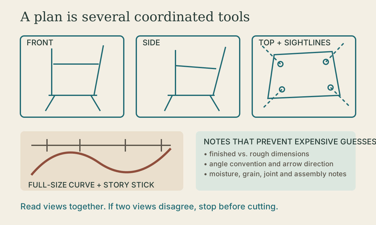
Choose one feature—a front leg mortise, for example—and find it in every view. The top view gives plan location and sightline. The front view gives side-to-side stance. The side view gives fore-and-aft stance and relationship to seat height.
Use a strip of tracing paper or a straightedge to project the point between views. If locations disagree:
- Check whether one view is diagrammatic rather than to scale.
- Check the revision dates.
- Prefer written dimensions over ruler measurements.
- Look for an errata sheet.
- Stop and resolve the conflict before cutting.
Galbert’s plan sets include full-size shapes, mortise locations, sightlines, and resultant angles precisely because chair geometry needs these views to cooperate 1.
Separate a pattern from a construction drawing
A pattern transfers a shape: crest curve, seat outline, arm, or turning profile. A construction drawing locates that part relative to the chair. A pattern may omit joint depth, grain direction, or final section because those belong elsewhere.
Lost Art Press explicitly notes that its full-size stick-chair pattern sheets show shapes, mortise locations, sightlines, and centerlines but do not replace the book’s construction information 2. Treat every plan package the same way: inventory what it supplies and what it assumes.
For a gridded pattern:
- Verify the grid interval.
- Draw a full-size grid on paper or thin plywood.
- Plot where the curve crosses each grid line.
- Fair the curve with a flexible batten; do not connect points with straight segments.
- Preserve the master and make a working copy.
Quick check
Lost Art Press notes its full-size pattern sheets don’t replace the book’s construction information.
Build a rod and story stick
A rod is a full-size drawing, often of one elevation. A story stick is a narrow strip carrying repeated locations: seat height, stretcher centers, rail shoulders, crest height.
They prevent arithmetic drift. Instead of measuring 12 3/8 inches on four posts, transfer one physical interval four times. Dividers can lift lengths and compound effects from the rod without converting them to decimals.
Make story-stick marks unambiguous:
- a knife line or fine pencil line for location;
- a V or arrow showing which side is waste;
- a label naming the feature;
- a face mark telling how to orient the stick;
- the project and revision date.
A mysterious tick mark is worse than no mark because it carries false authority.
Read the cut list as procurement, not prophecy
Chair parts often finish to the assembly:
- Stretchers fit the actual distance and angle between legs.
- Sticks fit actual seat and crest sockets.
- Wedges fit actual kerfs.
- Legs are left long and leveled after assembly.
- Curved blanks need extra width for grain-following layout.
Classify every cut-list value:
- Exact before assembly: seat blank thickness after milling.
- Leave proud: through-tenon length.
- Fit from the work: stretcher shoulder-to-shoulder distance.
- Allowance only: leg blank length before leveling.
Write the category beside the list. “Make to fit” is disciplined only when you know what controls the fit.
Quick check
Stretchers fit the actual distance and angle between legs; legs are left long and leveled after assembly.
Decode angles with arrows and words
An angle without a reference is incomplete. On your copy of a plan, rewrite every critical callout in words:
Rear leg: resultant 14° from seat normal, sightline 42° from seat centerline toward rear outside corner.
Add an arrow to the foot direction. Mirrored legs need mirrored arrows, not merely identical angle numbers. Lesson 3.3 derives the geometry; this lesson ensures the information survives paper-to-bench transfer.
Make a plan completeness audit
Before milling, locate each item:
| Question | Where answered? |
|---|---|
| Finished seat shape and thickness | top view + section |
| Leg mortise centers | seat plan |
| Sightline and angle convention | seat plan + note |
| Joint diameters and depths | detail or schedule |
| Curved-part grain direction | pattern note |
| Stretcher height | elevation or story stick |
| Assembly order | text |
| Parts left long for leveling | cut-list note |
| Moisture relationship | stock/joinery note |
An empty cell is a question to research or prototype, not an invitation to guess while glue is open.
Produce a repeatable plan from your prototype
After the design loop in Lesson 3.1:
- Establish a seat reference plane and centerlines.
- Draw full-size side and front elevations.
- Draw the seat plan with mortise centers and foot-direction arrows.
- Add full-size patterns for every non-geometric curve.
- Add joint sections at final dimensions.
- Create a cut list with fit categories and allowances.
- Write an assembly sequence and moisture notes.
- Add a revision block.
- Give the package to a “future builder” who did not watch the prototype—yourself after two weeks counts.
Try to reconstruct the chair using only the package. Every question reveals missing stored knowledge.
Exercise: decompress a real plan
Choose one chair from the free Stick Chair Book, whose published material includes complete plans and chairmaking context 3. On a separate sheet:
- list all views and patterns;
- create a story stick for vertical locations;
- rewrite one leg’s geometry in words;
- classify every cut-list length;
- circle the three operations requiring a sample.
The goal is not to copy marks. It is to turn a document into tooling, sequence, and decisions. When Views, Values, Vectors, and Sequence agree, the plan becomes a reliable second workshop.
Lesson complete
Nice work.
Sources for this lesson
- 1Peter Galbert. Chairmaker's Notebook. Lost Art Press. 2015. verifiedDetailed chairmaking reference for drilling, reaming, sightlines, and compound geometry. Cited at: plans and Appendix A.
- 2Revised Full-size Patterns from The Stick Chair Book. Lost Art Press. verifiedPublisher description of full-scale shapes, mortise locations, drilling sightlines, and centerlines intended for adaptation. Cited at: product description.
- 3Christopher Schwarz. The Stick Chair Book. 2nd revised ed. Lost Art Press. verifiedPublisher page with the complete book available as a free PDF. Cited at: Part III.