The Physics of Chairs
Chair structure in numbers: tracing load paths, moments as force times distance at the crest, why section depth cubed controls stiffness, joints as the narrowest point, strain in bent wood, load-testing prototypes with weights, and diagnosing failures by symptom.
- 8 min
- 9 steps
- 5 questions
- Lesson 121 of 160
In this lesson
- Path: draw force through actual members
- Moment: force multiplied by distance
- Section: stiffness is strongly directional
- Joint: the load path narrows
- Bending wood: limit strain by changing the system
- Load testing a prototype
- Diagnose by symptom
- A redesign checklist
Picking up where you left off.
A chair is a structure loaded by a moving person. Static body weight is only one case. Sitters arrive with momentum, lean on a tall back, drag the chair sideways, and sometimes support weight near one edge. That is why seating standards specify multiple structural and durability tests rather than a single “holds 250 pounds” claim 1.
The physics needed for design decisions fits into four questions:
- Path: where does force travel to the floor?
- Moment: what lever arm multiplies that force?
- Section: how does part shape resist bending?
- Joint: where do fibers and connections concentrate stress?
Path: draw force through actual members
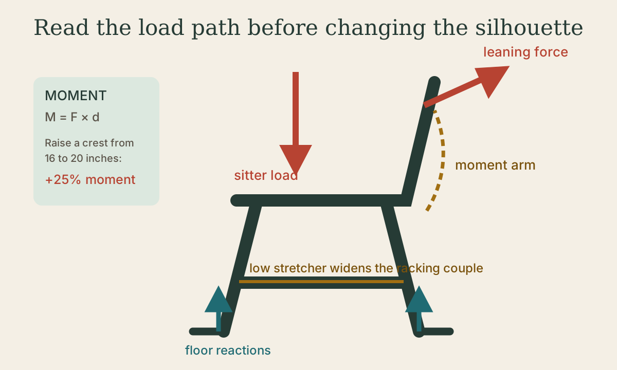
Begin with a downward arrow at the sitter. Follow it through seat, rails or sockets, legs, and feet. Then add a backward arrow at the crest and trace that load through posts or sticks into the seat structure.
If your pencil must jump across air or through upholstery that is not structural, the load path is incomplete. If several paths exist, show how they share load. A continuous rear post in a frame chair can carry from crest to floor; a stick chair transfers back load into a thick seat through multiple sockets.
Floor reactions act upward at the feet. The chair remains stable while the combined load falls within its support polygon—the polygon connecting floor contacts. Splay can enlarge that polygon, but a foot that projects far outward also increases leverage on its joint. Stability and joint stress must be considered together.
Quick check
Tipping is a geometry question: once the combined load crosses the edge of the support polygon, the chair rotates about that edge, no matter how strong its parts are.
Moment: force multiplied by distance
The turning effect of a force is a moment:
where \(d\) is the perpendicular distance from the force’s line of action to the point being considered. This is the same statics relationship taught in introductory mechanics 2.
Suppose a sitter exerts a 60-pound backward force near a crest 16 inches above the seat connection:
Raise the crest to 20 inches while everything else stays the same:
That is a 25% increase. The example is not a design load or safety rating; it shows why a four-inch aesthetic change is structurally meaningful.
The same logic explains racking. A side force at seat height tries to turn a rectangular leg frame into a parallelogram. A low stretcher and upper rail form a couple: separated resisting forces counter the racking moment. Moving the stretcher upward reduces that separation and requires larger joint forces to resist the same moment.
Quick check
M = F × d; 60 × 20 = 1,200. A four-inch aesthetic change is a structural change.
Section: stiffness is strongly directional
For a rectangular section bending about its centroidal axis, the second moment of area is
The cubed dimension \(h\) is measured in the bending direction. Turn a 1/2-by-1-inch slat ninety degrees and its stiffness changes dramatically.
Compare equal material rectangles:
- Flat: \(b=1\), \(h=0.5\), so \(I=1(0.5)^3/12\approx0.0104\text{ in}^4\)
- On edge: \(b=0.5\), \(h=1\), so \(I=0.5(1)^3/12\approx0.0417\text{ in}^4\)
The on-edge orientation is about four times as stiff in that bending direction. This does not mean it is four times as strong in every failure mode. Stiffness, strength, buckling, grain, defects, and joint geometry remain separate questions.
Chairmakers exploit section deliberately:
- a crest can be visually thin but deep in the direction of back force;
- a back slat can flex toward the sitter while remaining wide across the back;
- legs can taper away from joints, preserving section where moments are higher;
- several small sticks can share load and provide controlled flexibility.
Quick check
I = bh³/12: flat 0.0104 in⁴, on edge 0.0417 in⁴. Depth in the bending direction counts cubed.
Joint: the load path narrows
Connections concentrate stress because material is removed and forces change direction. Wood’s properties also differ sharply with grain direction; the USDA Wood Handbook provides species-specific values and distinguishes along-grain strength from perpendicular-to-grain and shear behavior 3.
Inspect four failure zones:
- Mortise wall: enough sound wood around the opening?
- Tenon shoulder: does it bear cleanly and reduce movement?
- Short grain: does a curve or notch leave fibers that exit quickly?
- Peel or withdrawal: is the connection relying on adhesive in an unfavorable direction?
Wedges, pins, tapers, and shrink fits add mechanical resistance. They do not excuse a poor fit. Galbert’s chairmaking system joins geometry, tapered sockets, and controlled assembly so the joint works as a complete mechanism 4.
Bending wood: limit strain by changing the system
For a thin strip bent to radius \(R\), a useful geometric approximation for outer-fiber strain is
where \(t\) is strip thickness. At a 10-inch radius:
- 1/2-inch stock: \(\epsilon\approx0.5/(20)=2.5\%\)
- 1/8-inch lamination: \(\epsilon\approx0.125/(20)=0.625\%\)
Thinner plies reduce strain in each layer; glue freezes the stack into a larger structural section. The equation is an idealized geometry check, not a species-specific safe-bending table. Grain, defects, moisture, temperature, adhesive, and springback all matter.
Steam bending changes wood behavior through heat and moisture. A compression strap can prevent the outer face from stretching freely, shifting more of the bend into compression. Again, good grain is non-negotiable. The USDA handbook treats wood’s moisture and mechanical response; chair-specific practice and forms are developed in Galbert’s bending chapter 3 4.
Quick check
At 10-inch radius, 1/2-inch stock strains about 2.5%, a 1/8-inch ply about 0.6%. Glue then locks the stack into a stiff section.
Load testing a prototype
Don’t improvise a dramatic test to failure on a finished chair, and don’t use a person as the test load. To check a prototype or sample:
- Inspect all joints, grain, wedges, and fasteners first.
- Strap or block the chair on a level floor.
- Add sandbags or weights in steps, standing clear of where broken parts would go.
- Unload after each step and measure deflection or movement at marked points.
- Stop at unexplained noise, opening joint lines, cracks, or permanent bending.
A one-time shop test finds gross defects. It doesn’t prove long-term durability; that’s what years of use and proven designs provide. For experimental joints, break sacrificial samples in a vise or fixture, where failure is safe and leaves readable evidence.
Diagnose by symptom
- Back feels loose only under lean: inspect the high-moment path into seat or rear posts.
- Chair racks side-to-side: identify which rectangle lacks an effective brace or force couple.
- One joint repeatedly opens: look for leverage, poor shoulder bearing, grain movement, or insufficient mechanical lock—not just weak glue.
- Part feels springy but returns: stiffness may be low while strength remains adequate; decide whether flexibility is intentional.
- Part remains bent after unloading: permanent set signals material or joint distress.
- Chair tips before joints strain: support polygon, not member strength, is governing.
A redesign checklist
Before changing a proven chair, write:
- What load path changes?
- What moment arm changes, by what percentage?
- Which section dimension resists the new bending direction?
- Which joint loses wall thickness or gains leverage?
- What sample will isolate the riskiest change?
Path, moment, section, and joint turn a visual edit into a structural question. Physics does not dictate one beautiful chair. It tells you which consequences must be paid for when the silhouette changes.
Practice
Splay widens the polygon, improving stability, but the longer lever arm raises the moment the leg applies to its joint. Stability and joint stress must be judged together.
Lesson complete
Nice work.
Sources for this lesson
- 1ANSI/BIFMA X5.1-2017(R2022): General-Purpose Office Chairs — Tests. Business and Institutional Furniture Manufacturers Association. verifiedOfficial scope summary for structural strength and durability testing of general-purpose seating. Cited at: X5.1 scope.
- 2University Physics, Volumes 1–3. OpenStax (Rice University). verifiedOpen calculus-based physics. Vol 1 mechanics; Vol 2 thermodynamics and electricity & magnetism; Vol 3 optics & modern physics. Cited at: Volume 1, torque and static equilibrium.
- 3Robert J. Ross. Wood Handbook: Wood as an Engineering Material. Revised 2021 ed. USDA Forest Service, Forest Products Laboratory. 2021. verifiedOfficial chapters on wood structure, moisture, mechanical properties, fastenings, composites, drying, and finishing. Cited at: Chapters 5, 8, and 9; Chapters 4 and 19.
- 4Peter Galbert. Chairmaker's Notebook. Lost Art Press. 2015. verifiedDetailed chairmaking reference for drilling, reaming, sightlines, and compound geometry. Cited at: Windsor Joinery and Undercarriage Joinery; Bending Wood.