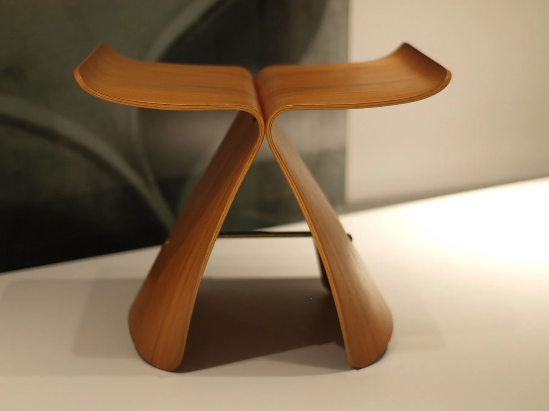
Bent Lamination: The Butterfly Homage
A derived study of Sori Yanagi's Butterfly stool in bent lamination: defining success, a reference board, calibrating and tracing photographs, designing the ply stack, a form stiffer than the lamination, gluing one shell as an experiment, and the center hardware.
- 7 min
- 9 steps
- 3 questions
- Lesson 137 of 160
In this lesson
- Define success before tracing
- Build a reference board
- Calibrate, trace, and fair
- Design the lamination stack
- Make a form that cannot negotiate
- Glue two shells as one experiment
- Hardware is part of the structure
- Load-test before use
Open alongside this lesson
-
Butterfly Stool (opens in a new tab)
Use for construction identity and form reading, not as a shop profile or plan.
-
Wood Handbook, Chapter 19: Specialty Treatments (opens in a new tab)
Stock selection, plasticizing, bending, and fixing principles; it does not supply this project's profile.
Picking up where you left off.
The Butterfly homage is the course’s bent-lamination exam. It is also a derived design exercise, not an authorized replica plan. Vitra identifies Sori Yanagi’s stool as molded plywood and describes its meeting of an Eastern form with twentieth-century plywood-molding technique 1. Your home-shop interpretation should keep that attribution visible and document every derived choice.
The goal is not to counterfeit an original. It is to produce two sound, mirrored curved shells; join them through a planned hardware system; and learn what full-size prototypes reveal about a seductive photograph.
.jpg)
Define success before tracing
The finished homage must:
- place both shells flat on a reference floor without forced twist;
- pass the weighted load test at the end of this lesson without glue-line opening, hardware movement, or permanent set;
- have edges comfortable to hands and legs;
- use mirrored parts from one controlled form or verified pair of forms; and
- include a build record labeled “after Sori Yanagi,” with the source images and your derived drawing.
Appearance is secondary to a sound lamination and stable stance. Do not use a first prototype as household seating merely because it resembles the icon.
Build a reference board
Collect three kinds of information:
- An official manufacturer or museum record for object identity and current overall data.
- Square-looking front and side photographs with known provenance.
- Your own decisions: intended seat use, available plywood/veneer, form method, hardware, and finish.
Photographs are perspective projections. A side that looks “square-on” can still enlarge the near edge and compress the far one. Use several views. If two calibrated traces disagree, preserve both until a full-size mock-up resolves the question.
Do not paste a manufacturer image into a vector program, trace one outline, and call it a plan. Label the file derived study, record the image URL and access date, and keep each transformation reversible.
Calibrate, trace, and fair
Pick an overall dimension published by the official source as the scale anchor. If that feature measures \(p\) pixels in the image and should represent \(D\) real units, the provisional scale is:
Multiply other pixel measurements by \(s\). This creates estimates, not truth. Perspective and lens distortion remain.
Trace the structural centerline of the shell before its outer edges. Offset to the intended shell thickness. A centerline is easier to fair than two independently wobbly outlines. Print the profile full size, cut it from cardboard or thin plywood, and place two mirrored copies on a floor.
Create a crude three-dimensional mock-up from sheet goods and temporary blocks. Use it only for visual and body-scale checks of seat height, upper width, foot spread, and the point where the shells meet; do not sit on or load it. Test posture separately with the fitting rig from Lesson 1.2, where clamps position unloaded parts only.
Mnemonic: scale, centerline, offset, mock-up.
Stop gate: at least two source views support the profile, the printed scale has been checked with a control dimension, and a full-size mock-up resolves the basic stance.
Quick check
s = D / p = 17.25 / 862 ≈ 0.020 in/px - valid only for features in that same plane.
Quick check
Two independently traced edges both carry wobble from the photo.
Design the lamination stack
Let finished shell thickness be \(T\), planned ply thickness be \(t\), and ply count be \(n\). Start with:
Then build a small stack from the actual material and measure its compressed, cured thickness. Veneer labels, sanding, glue lines, and pressure change the result. The tightest radius controls ply thickness. Use the comparative strain estimate \(t/(2R)\): thinner plies reduce strain, but increase glue lines and assembly time.
Choose material whose face orientation, internal plies, and adhesive are appropriate for bent structural furniture. Do not assume ordinary decorative veneer plus random construction plywood becomes equivalent to industrial molded plywood. Consult the material and adhesive makers when the construction is uncertain.
For shop-sawn solid plies, keep them in cutting order and mark a registration triangle. Cull runout, checks, knots, and planer tearout. For commercial veneers, inspect every sheet and mark face direction according to the layup design.
Make a form that cannot negotiate
The form must stay stiffer than the lamination. Build it on a flat base with enough ribs or solid layers that clamp pressure cannot flatten the curve. Fair the working surface with a long flexible batten and raking light. Any bump becomes a repeated feature in both shells.
Include:
- a centerline visible above and below the stack;
- end stops or registration marks;
- a release layer compatible with the adhesive;
- clamp access at the tightest radius;
- cauls broad enough to distribute pressure; and
- witness marks at points that must close.
Dry-clamp the complete stack. If it needs unsafe force or cannot seat at one station, change the form, cauls, or ply thickness. Glue is not a lubricant for bad geometry.
Estimate active glue-up time: spreading all plies + stacking + alignment + clamp sequence. Compare with the adhesive’s open time at actual shop temperature. If the estimate uses more than a comfortable fraction of that window, add a trained helper or choose a compatible longer-working adhesive. The USDA handbook emphasizes that wood condition, surface, adhesive, and process all determine bond performance 2.
Stop gate: the dry stack seats at every witness mark, the form does not deflect, all clamps are numbered in order, and the rehearsal fits safely within working time.
Glue two shells as one experiment
Make the first shell, record everything, then evaluate it before making the second:
- actual ply count and total thickness;
- adhesive batch, mix, spread method, temperature, and timestamps;
- clamp order and any location that resisted closure;
- time on the form and conditioning time after release; and
- springback at fixed measurement stations.
If the first part changes the form or process, it is now a prototype. Do not quietly make the second differently and force the pair together. Correct the cause and make a matched pair.
After cure, trim both shells with one template and reference from their structural centerlines. Avoid routing unsupported curved edges with a large exposed cutter. Use secure fixtures, shallow passes, and the safest tool sequence available; a bandsaw followed by controlled fairing may be preferable.
Quick check
Record ply count, adhesive batch, clamp order, and any spot that resisted closing.
Hardware is part of the structure
The shells meet at a compact center connection. Use the official object only to understand the design’s visible logic; engineer your shop hardware from sound material, appropriate bearing area, and accessible tightening. Do not infer hidden thread sizes from photographs.
Make a full-size connection sample from cutoff lamination. Drill with curved work fully supported in a cradle. Use backing to prevent exit damage. Provide washers, sleeves, or inserts where your design requires load to spread; keep metal edges from crushing a narrow veneer face. Locking methods must still allow inspection and repair.
Dry-assemble and place the stool on a known-flat surface. If one foot rises, do not tighten hardware until the twist disappears. Find whether the error is shell mismatch, hole location, form twist, or uneven trimming.
Load-test before use
Before anyone sits on a new chair, inspect every joint, then load the seat with sandbags or weights in steps, standing clear. Unload and look after each step; stop and diagnose if anything moves, cracks, ticks, or stays bent. A first chair that passes is fine to use and watch; an experimental one-off deserves a second look after some months of use.
Lesson complete
Nice work.
Sources for this lesson
- 1Sori Yanagi. Butterfly Stool. Vitra. verifiedManufacturer page for Yanagi's molded-plywood stool; use for construction identity and current overall product data, not shop-plan dimensions. Cited at: product description.
- 2Forest Products Laboratory. Wood Handbook: Wood as an Engineering Material. Revised 2021 ed. U.S. Department of Agriculture, Forest Service. 2021. verifiedOfficial engineering reference; chapters 4, 10, 13, 16, and 19 cover moisture, adhesives, drying, finishing, and plasticizing/bending. Cited at: chapter 10.
Further reading
- Wood Handbook, Chapter 19: Specialty Treatments. USDA Forest Service, Forest Products Laboratory. 2021. verifiedPublic U.S. government chapter covering plasticizing and bending wood, stock selection, the bending operation, and fixing the bend.
Previous: Stick Chair Warm-Up (*Build a Chair from Bulls%$t*)