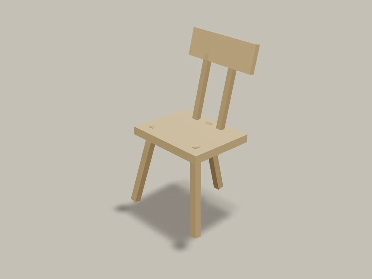
Complete Plan: The Three-Point Backstool
A complete original plan for a three-legged staked backstool: posture and a 102-degree seat-back angle, a seat coordinate map, boring angles measured from the seat normal, three joint samples, wedged through-tenons glued in two stages, and scribing feet.
- 18 min
- 21 steps
- 3 questions
- Lesson 144 of 160
In this lesson
- Fit first, then freeze the baseline
- Governing envelope
- Complete cut and material list
- Tool and fixture list
- Seat coordinate map
- Joint schedule
- Build sequence with stop gates
- Failure-prevention notes
- Definition of done and load test
Open alongside this lesson
-
The Stick Chair Book (opens in a new tab)
Publisher page with the complete book available as a free PDF.
-
Chairmaker's Notebook (opens in a new tab)
Detailed chairmaking reference for drilling, reaming, sightlines, and compound geometry.
-
Wood Handbook: Wood as an Engineering Material (opens in a new tab)
Official chapters on wood structure, moisture, mechanical properties, fastenings, composites, drying, and finishing.
-
Computer Workstations Purchasing Guide - Chairs (opens in a new tab)
Official office-workstation chair fit and adjustability criteria. The ranges are task-specific guidance, not universal dining, lounge, or one-off chair dimensions.
-
ANSI/BIFMA X5.1-2017(R2022): General-Purpose Office Chairs — Tests (opens in a new tab)
Official scope summary for structural strength and durability testing of general-purpose seating.
Picking up where you left off.
This original StudyCorner plan adds compound geometry and a restrained back to a thick-seat, staked structure. Three feet always define a plane, so the chair cannot develop the ordinary four-foot diagonal rock. That advantage has a cost: its support polygon narrows toward the single rear foot, making sideways perching near a rear corner less stable than on a wide four-legged frame.
All critical geometry is defined by coordinates, angles, and finished heights. No full-size printed pattern is required, and no number was scaled from the cited books or a photograph. The cited chairmaking sources explain fitting, sightlines, and compound-angle practice; the dimension network below is StudyCorner Plan TPB-1.0 1 2.
It’s not a step stool. Don’t stand on it, perch on a rear corner, tip it onto two feet, or lift it by the backboard.
Fit first, then freeze the baseline
The plan describes one compact upright posture, not a universal human average. OSHA’s office-chair purchasing guide is useful for understanding clearances, support, and adjustability, but its office-workstation ranges do not silently become dining-chair dimensions 3. Before milling structural stock, reproduce the following seat height, depth, rearward tilt, and 102-degree included back angle in the mechanically locked fitting rig from Lesson 1.2. Record the intended person and task.
If the baseline fails that fit check, stop. Changing seat height, back angle, seat depth, or the backboard station changes leg length, footprint, post length, and moments. That is a new documented design revision, not a casual shop correction.
Governing envelope
All dimensions are finished inches unless marked as blanks.
| Feature | Governing value |
|---|---|
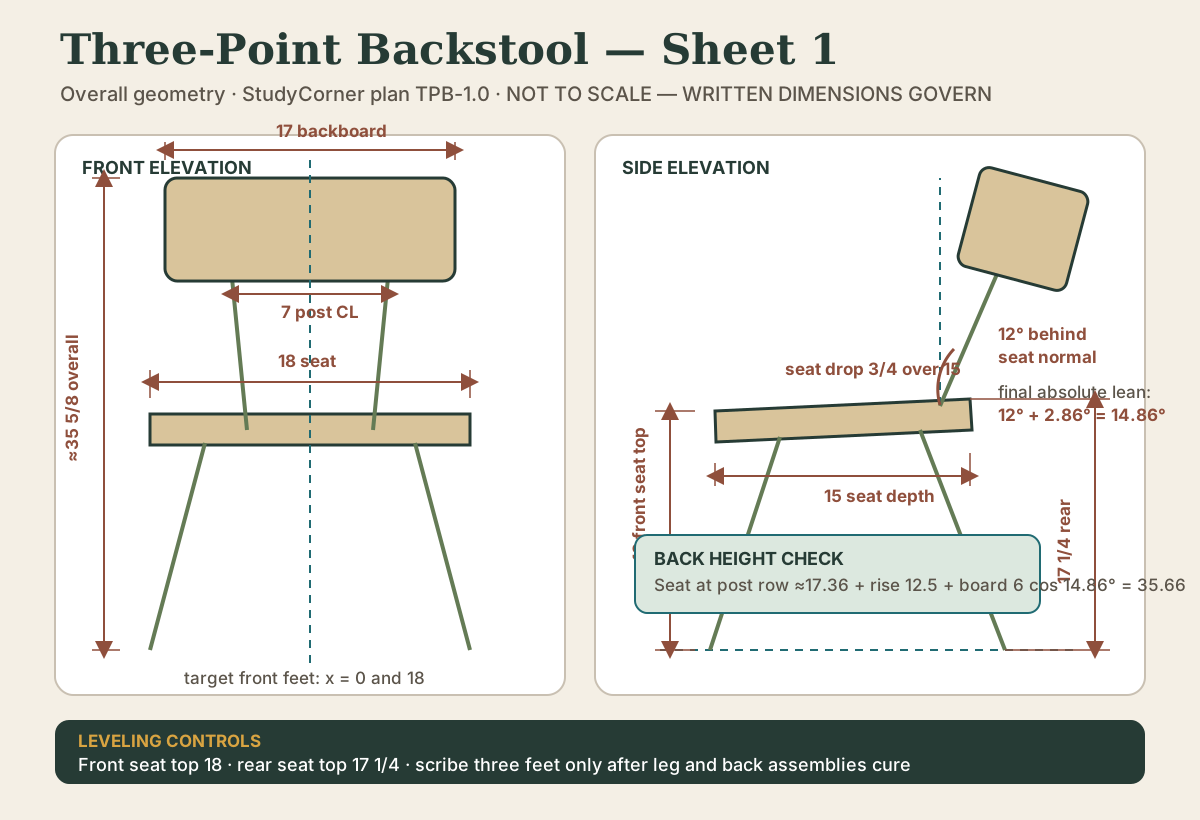
| Seat | 18 wide × 15 deep × 1 3/4 thick |
| Seat grain | Left-to-right across the 18-in. width |
| Front seat-top height after leveling | 18 |
| Rear seat-top height after leveling | 17 1/4 |
| Rearward seat drop | 3/4 over 15 |
| Approximate seat tilt | atan(.75 ÷ 15) = 2.86° |
| Back-post lean | 12° behind the seat normal |
| Included seat-to-back angle | Approximately 102° |
| Backboard | 17 wide × 6 high × 1 1/4 thick |
| Backboard position | Centered, leaving 1/2 in. each side of seat width |
| Backboard bottom | 12 1/2 vertical inches above seat at post row |
| Back-post center spacing | 7 |
| Target overall height | Approximately 35 5/8 after leveling |
| Seat corner radius | 1 |
| Front seat-edge round-over | 3/8 maximum |
| Backboard corner radius | 1 |
The 12-degree post angle is measured behind the seat normal. After the seat is leveled with a 2.86-degree rearward tilt, the seat normal is also 2.86 degrees behind floor vertical, so the posts and backboard stand approximately 12° + 2.86° = 14.86° behind floor vertical. The backboard’s six-inch height therefore contributes about 6 cos 14.86° = 5.80 inches vertically. At the post row, the seat top is about 17.36 inches above the floor; adding the 12.5-inch vertical rise to the backboard bottom and its 5.80-inch vertical height gives about 35.66 inches overall. The final height remains approximate because the feet are scribed after assembly; the front and rear seat heights are the leveling controls.
Do not saddle or deeply carve the version-1 seat. Preserve the full 1 3/4-inch thickness at every mortise and the entire rear joint field.
Quick check
Three points define a plane. Keep the sitter’s weight well inside the triangle.
Complete cut and material list
| ID | Part | Qty. | Finished or blank size | Joinery allowance |
|---|---|---|---|---|
| A | Seat | 1 | 1 3/4 × 18 × 15 finished | Five through mortises |
| B | Legs | 3 | 1 1/2 × 1 1/2 × 20 blanks | Shape to 1 1/8 minimum at feet; 1-in. upper tenons |
| C | Back posts | 2 | 1 1/4 × 1 1/4 × 18 blanks | 1-in. lower tenons; 3/4 × 1 3/8-in. upper tenons |
| D | Backboard | 1 | 1 1/4 × 6 × 17 | Two blind lower-edge mortises |
| E | Seat-joint wedges | 5 | 3/4 wide × 1 1/2 long × 3/16 maximum thick end | Fit from joint samples |
| F | Backboard pins | 2 | 1/4 diameter × 1 1/2 long | Trim after cure |
| G | Joint samples | 3 minimum | Match seat, leg/post, and backboard stock | One leg/seat, one post/seat, and one pinned backboard joint |
Legs may remain square with eased corners, become octagonal, or be turned, but the minimum stated sections and joint sizes remain. Do not introduce a taper that narrows a leg beside its seat joint. A straight taper may begin at least two inches below the seat transition and end at no less than 1 1/8 inches across the foot.
Board-foot calculation
Using rectangular envelopes:
| Group | Calculation | Finished bf |
|---|---|---|
| Seat | 1.75 × 18 × 15 ÷ 144 |
3.28 |
| Three leg blanks | 3 × 1.5 × 1.5 × 20 ÷ 144 |
0.94 |
| Two post blanks | 2 × 1.25 × 1.25 × 18 ÷ 144 |
0.39 |
| Backboard | 1.25 × 6 × 17 ÷ 144 |
0.89 |
| Total finished/blank envelope | 5.50 |
A plausible rough worksheet is 4.72 bf for a 2 × 20 × 17 seat blank, 1.34 bf for three 1.75 × 1.75 × 21 leg blanks, 0.59 bf for two 1.5 × 1.5 × 19 post blanks, and 1.31 bf for a 1.5 × 7 × 18 backboard blank. Those ideal rectangles total about 7.96 bf. Purchase 9 to 10.5 bf, and more if the available boards do not yield five exceptionally straight-grained slender parts.
Use sound, dry seat stock with no check entering the rear joint field. Use straight-grained ash, oak, hard maple, hickory, or similarly suitable stock for legs and posts. Species names do not override the actual board: reject short grain, knots, splits, decay, and severe runout. The Forest Products Laboratory documents wood’s directional structure, moisture movement, and highly variable mechanical properties 4.
Tool and fixture list
In addition to ordinary milling and marking tools, prepare:
- a full-size fitting rig;
- one story stick for the seat coordinate system;
- a bevel gauge or fixed guides for 12°, 13°, and 16° from the seat normal;
- a long straight sightline rule;
- a rigid platform that clamps the seat with the boring face visible;
- a matched 1-inch bit and tenon-sizing method;
- a matched 3/4-inch bit and upper-tenon sizing method;
- three distinct joint samples: one leg/seat, one post/seat, and one pinned post/backboard joint, all matching production thicknesses and tooling;
- backing board under through holes;
- saw or other controlled method for wedge kerfs;
- clamps for the two-post back assembly; and
- a flat floor/reference platform, shims, and scribing block.
Never hold the seat while compound drilling. Clamp it so neither it nor the backing board can turn. Keep hands out of the exit path. Do not feed unsupported round, octagonal, or tapered stock between a table-saw blade and fence. Use guarded, manufacturer-approved workholding and keep dust collection operating.
Seat coordinate map
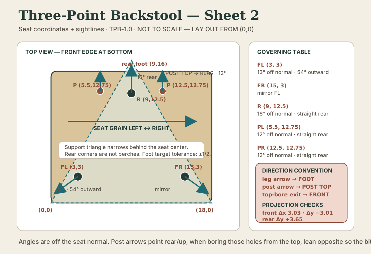
Set the finished seat blank top-up with its front-left corner as (0,0). The x-axis runs left-to-right across 18 inches; the y-axis runs front-to-back across 15 inches. Draw every sightline longer than the drill body.
| Joint | Center (x,y) |
Sightline on seat | Resultant angle |
|---|---|---|---|
| Front-left leg | (3, 3) |
54° outward from the forward centerline, in the front-left quadrant | 13° off seat normal |
| Front-right leg | (15, 3) |
Mirror of front-left, in the front-right quadrant | 13° off seat normal |
| Rear leg | (9, 12.5) |
Straight rear toward (9,16) |
16° off seat normal |
| Left back post | (5.5, 12.75) |
Straight rear | 12° off seat normal |
| Right back post | (12.5, 12.75) |
Straight rear | 12° off seat normal |
Direction convention: each leg sightline points from its seat-mortise center toward that leg’s foot—the downward part-axis projection. Each back-post sightline points from its mortise center toward the post top—the upward part-axis projection. Therefore, when a back-post mortise is bored from the seat top, the bit must lean opposite the rear-pointing post arrow and exit the underside toward the front. Label both POST TOP → REAR and BIT EXIT → FRONT before boring; never infer the feed direction from an unlabeled line.
The leg directions account for the leveled seat normal being 2.86 degrees behind floor vertical. At the front mortise row, the seat underside is approximately 16.10 inches above the floor. A 13-degree resultant along a sightline 54 degrees outward from forward projects approximately 3.03 inches outward and 3.01 inches forward, carrying (3,3) and (15,3) to the two front targets.
At the rear-leg mortise, the underside is approximately 15.63 inches above the floor. A 16-degree resultant directed straight rear projects about 3.65 inches rearward, carrying (9,12.5) to approximately (9,16.15), within the target tolerance. These are vector projections relative to the tilted seat plane; the simpler expression H tan(angle) would be wrong here because it silently treats the seat normal as floor vertical.
These foot coordinates are verification targets with a ±1/2-inch working tolerance, not instructions to cut three equal leg lengths. Seat tilt, shoulder fitting, and final scribing alter the actual endpoints. Leave all legs long, establish the specified seat attitude after cure, then scribe the common floor plane.
The intended support triangle connects front targets (0,0) and (18,0) with rear target (9,16). It is wide at the front and narrow near the back. The seat center lies inside; either rear corner lies outside. That is why this design forbids side-perching near the back.
Built from nothing but the seat map, a 3D mock-up lands its feet within this plan’s own 1/2-inch working tolerance of (0,0), (18,0), and (9,16), and its top within a quarter inch of the target height. That is a useful check on your arithmetic before you drill: if your own layout disagrees with the mock-up by more than the tolerance, find out why on paper first.
Joint schedule
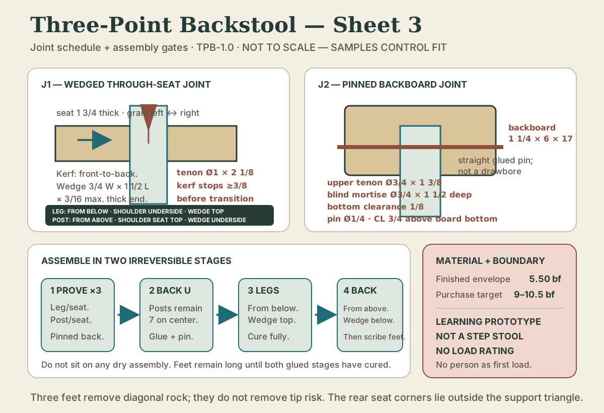
Legs through seat A
- Mortises: 1 inch diameter, through the 1 3/4-inch seat, at the stated centers and angles.
- Tenons: 1 inch diameter × 2 1/8 inches long.
- Fit: firm hand pressure in the leg/seat sample; no damaging dry-drive.
- Entry and shoulder: insert each leg from below, scribe its transition against the angled seat underside, and pare for broad contact. Do not rely on one sharp shoulder corner.
- Kerf: centered, stopping at least 3/8 inch before the tenon transition.
- Kerf direction: front-to-back on the installed chair.
- Wedge: straight-grain hardwood, 3/4 inch wide, 1 1/2 inches long, and no more than 3/16 inch at its thick end before fitting; drive it from the seat top.
Back posts through seat A
- Mortises: 1 inch diameter, through the 1 3/4-inch seat, at the stated centers and 12-degree angle.
- Lower tenons: 1 inch diameter × 2 1/8 inches long.
- Fit: firm hand pressure in the separate post/seat sample; no damaging dry-drive.
- Entry and shoulder: insert the cured U-shaped back assembly from above, scribe each lower-post transition against the angled seat top, and pare for broad contact.
- Kerf: centered front-to-back, stopping at least 3/8 inch before the transition.
- Wedge: use the same maximum blank size, but drive it from the seat underside after the top shoulders close.
At 12 degrees, the mortise chord through the 1 3/4-inch seat is 1.75 ÷ cos 12° = 1.79 inches; a 2 1/8-inch lower tenon therefore projects about 0.34 inch below the underside for wedging. With a 12.94-inch exposed post axis and the 1 3/8-inch upper tenon, the required post length is 2.125 + 12.94 + 1.375 = 16.44 inches, so the 18-inch blank retains fitting and trimming allowance.
Seat grain runs left-to-right. For both joint types, a front-to-back kerf lets the wedge expand the tenon mainly left-to-right, parallel to the seat grain. Rotating the kerf 90 degrees encourages cross-grain splitting. Each wedge is driven only until its correctly located shoulder closes and the matching sample-established fit is reached; it is not driven until its thick end disappears.
Posts C into backboard D
- Upper post tenons: 3/4 inch diameter × 1 3/8 inches long.
- Blind mortises: 3/4 inch diameter × 1 1/2 inches deep, bored square into the backboard’s lower edge.
- Bottom clearance: the shorter tenon leaves 1/8 inch for glue and debris; do not lengthen the tenon to consume it.
- Backboard mortise centers: 5 and 12 inches from its left end.
- Post center spacing: 7 inches.
- Backboard bottom: 12 1/2 vertical inches above the seat at the post row.
- Exposed post distance along its final axis:
12.5 ÷ cos 14.86° = 12.94 inches. The mortises are still bored 12 degrees behind the seat normal. - Cross pins: 1/4 inch diameter, drilled front-to-back through the backboard and centered on each upper tenon 3/4 inch above the board’s bottom edge.
The cross pins are straight, glued locks, not offset drawbores. Drill them only after the backboard shoulders are seated and the two posts are parallel.
Build sequence with stop gates
1. Approve the posture and stock
Test the seat envelope and 102-degree included angle in the locked fitting rig. Inspect every structural blank along four faces. Mark defects and grain direction before cutting.
Stop gate: the intended user/task is recorded, the baseline posture is accepted without structural improvisation, and all five slender blanks have continuous grain through their joint zones.
2. Mill the seat but preserve the datums
Glue the seat blank if required, flatten it to 1 3/4 inches, and square it to 18 × 15 inches. Mark front, left, top, grain direction, and (0,0). Do not round corners or carve the seat yet.
3. Make three complete joint samples
Make three physically separate samples with the production stock thicknesses, cutters, adhesive, and wedge or pin stock:
- A leg/seat sample at a governing leg angle: insert the tenon from below, fit its shoulder to the underside, and drive the wedge from the top.
- A post/seat sample at 12 degrees: insert the tenon from above, fit its shoulder to the top, and drive the wedge from the underside.
- A pinned post/backboard sample: fit a 3/4 × 1 3/8-inch tenon in a 1 1/2-inch-deep blind mortise, close the shoulder, then drill and glue a 1/4-inch straight pin centered 3/4 inch above the backboard’s bottom edge.
After cure, section or inspect the two wedged samples for broad shoulder contact, splitting, glue starvation, and wedge travel. Inspect the pinned sample for full shoulder contact, its 1/8-inch bottom clearance, pin placement, and intact mortise cheeks.
Stop gate: all three samples close without a crack, neither wedged tenon can be withdrawn by hand, the pinned sample has no split cheek, and the three recorded fits become the production targets. These prove workmanship only, not chair capacity.
4. Transfer coordinates and rehearse angles
Mark all five centers from the front-left datum and independently verify mirrored x-dimensions. Extend sightlines and add the leg-foot versus post-top direction labels. On a separate full-thickness aiming block, bore each distinct direction and insert a straight test rod. Project the rod over the intended vertical run.
Stop gate: front test projections land within 1/4 inch of their calculated component targets, the rear test points rearward rather than forward, and every angle note states off seat normal.
5. Bore before shaping
Clamp the seat and backing board to the boring platform. Bore the front-left and front-right holes as mirrored operations, then the rear leg. For the two parallel back-post holes bored from the top, lean the bit opposite the rear-pointing post-top sightline so it exits the underside toward the front. Clear chips without levering the bit against a mortise wall.
Insert loose test rods and inspect from front, side, and top. Do not enlarge a correctly sized hole to average a bad direction. A materially misdirected structural mortise rejects the seat or triggers a competent redesign.
6. Shape and fit the lower structure
Round the four seat corners to the stated one-inch radius and ease the front edge to no more than a 3/8-inch round-over. Shape legs and posts, retaining full section near joints. Fit and number each lower tenon. During gentle dry fits, scribe each leg transition to the seat underside and each post transition to the seat top. Cut and label five wedges, preserving which three drive from above and which two drive from below.
With all three legs installed dry but unwedged, compare their projected footprint to the target triangle. Do not sit on this dry assembly.
Stop gate: all tenons seat to their reference lines, the target footprint is within the stated working tolerance, and no leg is being bent to improve appearance.
7. Make the back assembly
Mill the backboard, round its corners to one inch, and bore the two lower-edge mortises at five and twelve inches from the left end. Cut upper post tenons only after lower-post fit and exposed length are established.
Dry assemble the U-shaped back. The post centers must remain seven inches apart, and the backboard must seat without drawing them inward or pushing them apart. Glue the upper joints, clamp square to the post plane, then drill and glue the two 1/4-inch cross pins after shoulders close. Cure fully.
8. Glue in two controlled stages
First insert and glue the three legs from below, close their shoulders against the seat underside, and drive their wedges from the seat top. Recheck projected directions before the wedges become irreversible. Trim only the wedge excess after cure; leave the feet long.
Second, lower the cured back subassembly into the two seat mortises from above, close both shoulders against the seat top, then glue and wedge the lower tenons from the underside. Confirm both posts share the 12-degree plane and the backboard remains centered. Cure according to the adhesive instructions.
Quick check
Check projected directions before the wedges make the joints irreversible.
9. Establish attitude, then scribe feet
On a verified flat surface, shim the cured chair until the front seat top is 18 inches and the rear is 17 1/4 inches. Confirm the back remains centered. Set a scribing block from the highest floor gap and mark all three feet from that one plane. Trim outside the lines and creep up.
Three points cannot rock, but they can still be trimmed into the wrong seat attitude. The heights govern, not equal leg length.
10. Finish and document
Ease splinters without thinning structural sections. Test finish on offcuts, ventilate, and honor the complete cure schedule. Photograph front, sides, rear, underside, seat joint field, backboard pins, and the floor footprint. Record material, moisture observations, angles, joint samples, deviations, adhesive, finish, and cure dates.
Failure-prevention notes
- Angle read from floor vertical: produces the wrong leg field after seat tilt. All boring angles are off the seat normal.
- Both front legs aimed the same direction: destroys the mirror. Draw arrows from each mortise to its own target foot.
- Rear leg aimed forward: removes rear support exactly where back force acts. Its sightline is straight rear.
- Kerf rotated across seat grain: encourages a seat split. Kerfs run front-to-back.
- Wedge driven to a visual depth: can split even a good seat. The joint sample controls wedge taper and travel.
- Backboard used as a clamp: bowed posts store stress. The U assembly must close without changing seven-inch centers.
- Dry chair sat upon: unwedged cylindrical joints can release suddenly. Don’t sit on a dry-fitted chair.
- A rear corner treated as a perch: moves the sitter outside the triangular support polygon.
- Backboard used to drag the chair: applies a high moment to two post joints. Lift it under the seat.
Quick check
Reading angles from floor vertical after seat tilt produces the wrong leg field.
Definition of done and load test
Version 1 is complete when the seat reaches its two governing heights, all three feet contact the verified plane, the backboard is centered on parallel posts, no joint shows a crack or opening, edges are nonabrasive, and finish is cured.
Before anyone sits on it, inspect the support triangle, five seat joints, both cross pins, grain around every mortise, and the floor contact. Then load the seat with weights in steps, standing clear, and unload and inspect after each step. Stop at any movement, crack, or tick. Sit squarely: three-legged stools tip if you perch near a rear corner.
Lesson complete
Nice work.
Sources for this lesson
- 1Christopher Schwarz. The Stick Chair Book. 2nd revised ed. Lost Art Press. verifiedPublisher page with the complete book available as a free PDF. Cited at: chair comfort and geometry chapters.
- 2Peter Galbert. Chairmaker's Notebook. Lost Art Press. 2015. verifiedDetailed chairmaking reference for drilling, reaming, sightlines, and compound geometry. Cited at: boring, sightlines, and joint-fitting chapters.
- 3Computer Workstations Purchasing Guide - Chairs. Occupational Safety and Health Administration. verifiedOfficial office-workstation chair fit and adjustability criteria. The ranges are task-specific guidance, not universal dining, lounge, or one-off chair dimensions. Cited at: chair criteria.
- 4Robert J. Ross. Wood Handbook: Wood as an Engineering Material. Revised 2021 ed. USDA Forest Service, Forest Products Laboratory. 2021. verifiedOfficial chapters on wood structure, moisture, mechanical properties, fastenings, composites, drying, and finishing. Cited at: chapters 3–5.
Further reading
- ANSI/BIFMA X5.1-2017(R2022): General-Purpose Office Chairs — Tests. Business and Institutional Furniture Manufacturers Association. verifiedOfficial scope summary for structural strength and durability testing of general-purpose seating.